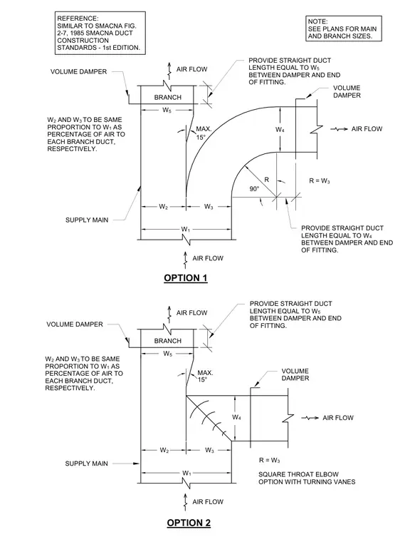
Two configuration options split a main HVAC supply duct into branch ducts with proportional sizing rules. Option one incorporates a curved fitting with a maximum fifteen-degree transition angle, while option two utilizes a square throat elbow equipped with turning vanes. Both options dictate that branch widths W2 and W3 maintain the same proportion to main width W1 as the percentage of airflow destined for each respective branch duct. Volume dampers are positioned on branch runs requiring straight duct lengths equal to the respective branch width between the damper and the fitting end. Reference standards follow SMACNA figure two dash seven from the nineteen eighty-five duct construction standards.
NOTE: SEE PLANS FOR MAIN AND BRANCH SIZES. PROVIDE STRAIGHT DUCT LENGTH EQUAL TO W 5 BETWEEN DAMPER AND END OF FITTING. W 5 AIR FLOW AIR FLOW BRANCH VOLUME DAMPER 15° MAX. W 4 W 1 W 2 W 3 SUPPLY MAIN 90° R R = W 3 PROVIDE STRAIGHT DUCT LENGTH EQUAL TO W 4 BETWEEN DAMPER AND END OF FITTING. REFERENCE: SIMILAR TO SMACNA FIG. 2-7, 1985 SMACNA DUCT CONSTRUCTION STANDARDS - 1st EDITION. AIR FLOW W 2 AND W 3 TO BE SAME PROPORTION TO W 1 AS PERCENTAGE OF AIR TO EACH BRANCH DUCT, RESPECTIVELY. VOLUME DAMPER AIR FLOW AIR FLOW BRANCH 15° MAX. SUPPLY MAIN AIR FLOW SQUARE THROAT ELBOW OPTION WITH TURNING VANES W 5 W 4 W 2 W 3 W 1 W 2 AND W 3 TO BE SAME PROPORTION TO W 1 AS PERCENTAGE OF AIR TO EACH BRANCH DUCT, RESPECTIVELY. PROVIDE STRAIGHT DUCT LENGTH EQUAL TO W 5 BETWEEN DAMPER AND END OF FITTING. VOLUME DAMPER R = W 3 VOLUME DAMPER OPTION 1 OPTION 2
Members view this detail in full resolution, download the CAD files (SVG, PDF), and can adapt it in the built-in CAD editor — export DXF, DWG, or PDF.
Start membership