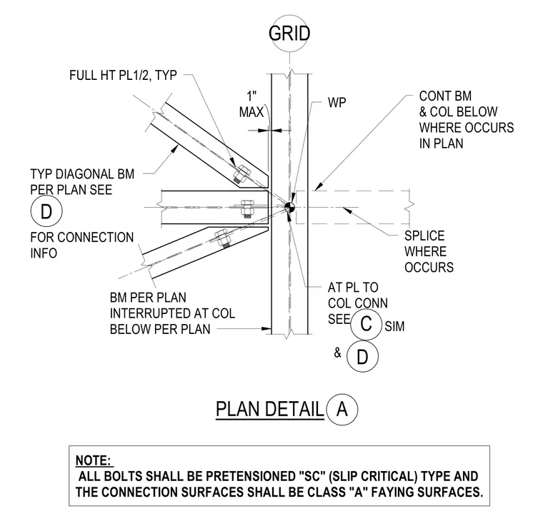
This plan detail shows a typical horizontal diagonal beam bracing connection intersecting a column at a work point. Typical diagonal beams frame into full-height one-half-inch plates with a one-inch maximum clearance. A continuous beam and column run below where indicated in the plan, featuring a splice where it occurs. All bolts must be pretensioned slip-critical type with Class A faying surfaces.
A PLAN DETAIL BM PER PLAN INTERRUPTED AT COL BELOW PER PLAN WP TYP DIAGONAL BM PER PLAN SEE FOR CONNECTION INFO 1" MAX GRID SPLICE WHERE OCCURS AT PL TO COL CONN SEE C SIM & CONT BM & COL BELOW WHERE OCCURS IN PLAN NOTE: ALL BOLTS SHALL BE PRETENSIONED "SC" (SLIP CRITICAL) TYPE AND THE CONNECTION SURFACES SHALL BE CLASS "A" FAYING SURFACES. D D FULL HT PL1/2, TYP
Members view this detail in full resolution, download the CAD files (SVG, PDF), and can adapt it in the built-in CAD editor — export DXF, DWG, or PDF.
Start membership