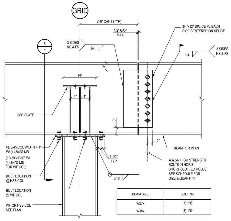
A steel beam connection is supported by a wide-flange or hollow structural section column sized per plan with a two-foot cantilever typical. A three-quarter-inch plate measuring three-quarters of an inch by the column width plus one inch connects with four three-quarter-inch diameter machine bolts for wide-flange columns. Splice plates measuring three-quarters of an inch by twelve inches are centered on the splice on each side, utilizing A325-N high-strength bolts in horizontal short-slotted holes with sizes and quantities per the schedule. Fillet welds of one-quarter-inch and five-sixteenth-inch sizes are applied on three sides near side and far side as specified. A maximum one-half-inch gap is maintained at the joint, with bolt locations explicitly designated for both hollow structural section and wide-flange columns.
4" 4" 2" WF OR HSS COL SEE PLAN 2'-0" CANT (TYP) 3" 5/16 GRID 14" 3/4" PLATE 1/4 1/2" GAP MAX 3 SIDES NS & FS 3/4"x12" SPLICE PL EACH SIDE CENTERED ON SPLICE BEAM PER PLAN A325-N HIGH STRENGTH BOLTS IN HORIZ SHORT-SLOTTED HOLES, SEE SCHEDULE FOR SIZE & QUANTITY 5 - (1"x20"x1'-10" W/ (4) 3/4"Ø MB FOR WF COL) 1/4 3" PL 3/4"xCOL WIDTH + 1" W/ (4) 3/4"Ø MB 1 1/2" TYP BOLT LOCATION @ HSS COL BOLT LOCATION @ WF COL BEAM SIZE BOLTING W27x (7) 1"Ø W30x (8) 1"Ø 3 SIDES NS & FS
Members view this detail in full resolution, download the CAD files (SVG, PDF), and can adapt it in the built-in CAD editor — export DXF, DWG, or PDF.
Start membership