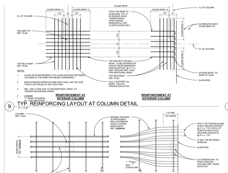
Typical top and bottom mild reinforcing and banded post-tensioned tendon layout at interior and exterior column locations within a concrete slab. Mild reinforcement is distributed within dimension lines defined by column widths and multiples of slab thickness, alternating every other bar with a maximum spacing of twelve inches on center. Top bars terminate at the slab edge with a ninety-degree downward hook, and bar extensions from the column face must meet or exceed a lap splice length. Banded tendons are arranged with a maximum of five per bundle and spaced at a minimum of four inches between bundles, passing through column vertical reinforcement with minimum counts per column width. Slab edges and anchor placements are detailed based on slab thickness, with specific curvature requirements for tendon layouts.
ALTERNATE EVERY OTHER BAR TYP. CL OF COLUMN SLAB EDGE TOP AND BOTTOM MILD REINF. TO BE DISTRIBUTED WITHIN THESE DIMENSION LINES EACH WAY @ 12" o.c. MAX. SPACING REF. PLAN FOR ADDITIONAL REINF. REINFORCEMENT AT INTERIOR COLUMN NOTES: 1. CLEAR SPAN REPRESENTS THE CLEAR DISTANCE BETWEEN COLUMNS IN THE DIRECTION BEING CONSIDERED. 2. BAR EXTENSION FROM COLUMN FACE SHALL NOT BE LESS THAN A LAP SPLICE AT ANY LOCATION. 3. REF. 2/S5.12 AND 5/S5.12 FOR ADDITIONAL REINF. AT TENDON ANCHORAGE ZONES. 4. LEGEND T = SLAB THICKNESS W = COLUMN WIDTH TOP MILD REINF. REF. PLAN REINFORCEMENT AT EXTERIOR COLUMN COLUMN TYP. REF. PLAN TOP MILD REINF. REF. PLAN EXTEND REINF. TO EDGE OF SLAB HOOK TOP BARS AT SLAB EDGE TYP. w/ 90 DEGREE HOOK TURNED DOWN HOOK SHOWN HORIZONTAL FOR CLARIFICATION ONLY 1.5T W 1.5T 1.5T W 1.5T W 1.5T 1.5T W 1.5T CL OF COLUMN CL OF COLUMN FULLY SUPPORT ALL REINF. TAILS AT PROPER ELEVATION CLEAR SPAN / 4 CLEAR SPAN / 4 CLEAR SPAN CLEAR SPAN / 4 CLEAR SPAN / 4 CLEAR SPAN / 4 SLAB EDGE BANDED TENDONS (5) PER BUNDLE MAX. DISTRIBUTE EVENLY WITHIN BAND WIDTH REF. SC080.06 COLUMN REF. PLAN (2) TENDONS MIN. TO PASS THROUGH COLUMN VERT. REINF. EACH WAY FOR 7" OR THICKER SLABS PLACE ANCHOR UPRIGHT @ 3" o.c. TYP. FOR 6 1/2" SLAB OR LESS PLACE ANCHORS SIDEWAYS @ 6" o.c. TYP. 12 1 MAX. CURVATURE TO CURVE 1'-0" MIN. BAND WIDTH . . 4" MIN. TYP BETWEEN BUNDLES REF. SC080.06 1" = 1'-0" 9 TYP. REINFORCING LAYOUT AT COLUMN DETAIL
Members view this detail in full resolution, download the CAD files (SVG, PDF), and can adapt it in the built-in CAD editor — export DXF, DWG, or PDF.
Start membership