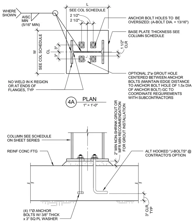
A structural steel column bears on a base plate atop a reinforced concrete footing, secured by four one-inch diameter anchor bolts with three-eighths thick by three-inch square plate washers. The base plate thickness and overall dimensions are sized per the column schedule, featuring oversized anchor bolt holes and an optional two-inch diameter grout hole centered between bolts while maintaining a minimum edge distance equal to one and a half times the bolt diameter. An alternate hooked J-bolt option is provided at the contractor's discretion for grout installation. A minimum two-inch non-shrink grout layer is detailed beneath the base plate, resting on the reinforced concrete footing which maintains three inches of concrete cover. Welds connecting the column to the base plate adhere to AISC minimum standards with a five-sixteenths inch minimum fillet weld, leaving the K region and flange ends unwelded.
SEE COL SCHEDULE L 2 1/2" 2 1/2" CLR 1 1/2" SEE COL SCHEDULE W ANCHOR BOLT HOLES TO BE OVERSIZED: (A-BOLT DIA. + 13/16") BASE PLATE THICKNESS SEE COLUMN SCHEDULE OPTIONAL 2"ø GROUT HOLE CENTERED BETWEEN ANCHOR BOLTS (MAINTAIN EDGE DISTANCE TO ANCHOR BOLT HOLE OF 1.5x DIA OF ANCHOR BOLT) GC TO COORDINATE REQUIREMENTS WITH SUBCONTRACTORS AISC WHERE SHOWN NO WELD IN K REGION OR AT ENDS OF FLANGES, TYP CL MIN (5/16" MIN) 3" 3" COLUMN SEE SCHEDULE ON SHEET SERIES REINF CONC FTG (4) 1"Ø ANCHOR BOLTS W/ 3/8" THICK x 3" SQ PL WASHER TYP 3" CLR, ALT HOOKED "J-BOLTS" @ CONTRACTO'S OPTION FOR GROUT INSTALLATION 2" MIN NON-SHRINK GROUT OR MFR MIN RECOMMENDATION 1" = 1'-0" 4A PLAN
Members view this detail in full resolution, download the CAD files (SVG, PDF), and can adapt it in the built-in CAD editor — export DXF, DWG, or PDF.
Start membership