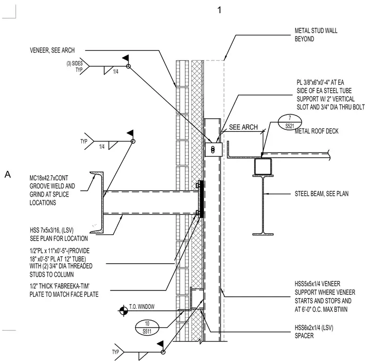
Eyebrow framing and veneer support assembly tied back to the primary structural steel system. An MC18x42.7 channel with continuous groove welds ground smooth at splice locations connects to an HSS 7x5x3/16 tube. A half-inch thick plate measuring 11 inches by 5 inches features two three-quarter-inch diameter threaded studs attaching to the column, with an eighteen-inch plate provided at twelve-inch tubes. A half-inch thick Fabreeka-Tim pad matches the face plate profile. HSS 5x5x1/4 veneer support tubes are positioned where the veneer starts and stops, spaced at a maximum of six feet on center. Three-eighths-inch thick by six-inch by four-inch plates are located at each side of each steel tube support, featuring a two-inch vertical slot and a three-quarter-inch diameter through bolt. An HSS 6x2x1/4 structural spacer sits adjacent to a metal stud wall, while the metal roof deck bears on a steel beam.
METAL STUD WALL BEYOND METAL ROOF DECK STEEL BEAM, SEE PLAN T.O. WINDOW TYP HSS6x2x1/4 (LSV) SPACER HSS5x5x1/4 VENEER SUPPORT WHERE VENEER STARTS AND STOPS AND AT 6'-0" O.C. MAX BTWN (3) SIDES 1/4 TYP TYP 1/4 1/2" THICK 'FABREEKA-TIM' PLATE TO MATCH FACE PLATE 1/2"PL x 11"x0'-5"-(PROVIDE 18" x0'-5" PL AT 12" TUBE) WITH (2) 3/4" DIA THREADED STUDS TO COLUMN MC18x42.7xCONT GROOVE WELD AND GRIND AT SPLICE LOCATIONS HSS 7x5x3/16, (LSV) SEE PLAN FOR LOCATION PL 3/8"x6"x0'-4" AT EA SIDE OF EA STEEL TUBE SUPPORT W/ 2" VERTICAL SLOT AND 3/4" DIA THRU BOLT VENEER, SEE ARCH 10 S511 7 S521 SEE ARCH A 1
Members view this detail in full resolution, download the CAD files (SVG, PDF), and can adapt it in the built-in CAD editor — export DXF, DWG, or PDF.
Start membership