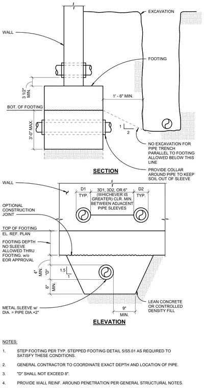
Pipe penetrations and trenching configurations at concrete wall footings. Pipes pass through the wall and footing utilizing metal sleeves with diameters equal to the pipe diameter plus two inches, complete with a collar to keep soil out of the sleeve. Clearances between adjacent pipe sleeves must be at least three times the diameter of the larger pipe, three times the diameter of the smaller pipe, or six inches, whichever is greater. Excavation for pipe trenches parallel to the footing must maintain a one-to-two slope line below the footing level and is restricted from extending below specified depths without engineer of record approval. Lean concrete or controlled density fill is provided below stepped portions of the footing where required.
MIN. 3 1/2" MIN. 9" MIN. 6" "D" MIN. 4" NO EXCAVATION FOR PIPE TRENCH PARALLEL TO FOOTING ALLOWED BELOW THIS LINE 1 2 EXCAVATION PROVIDE COLLAR AROUND PIPE TO KEEP SOIL OUT OF SLEEVE SECTION ELEVATION METAL SLEEVE w/ DIA. = PIPE DIA.+2" TOP OF FOOTING 3D1, 3D2, OR 6" (WHICHEVER IS GREATER) CLR. MIN. BETWEEN ADJACENT PIPE SLEEVES WALL FOOTING NOTES: 1. STEP FOOTING PER TYP. STEPPED FOOTING DETAIL 5/S5.01 AS REQUIRED TO SATISFY THESE CONDITIONS. 2. GENERAL CONTRACTOR TO COORDINATE EXACT DEPTH AND LOCATION OF PIPE. 3. "D" SHALL NOT EXCEED 8". 4. PROVIDE WALL REINF. AROUND PENETRATION PER GENERAL STRUCTURAL NOTES. OPTIONAL CONSTRUCTION JOINT LEAN CONCRETE OR CONTROLLED DENSITY FILL 1.5 1 1' - 6" MIN. 3'-0" MAX. BOT. OF FOOTING TYP. D2 1' TYP. D1 WALL FOOTING DEPTH NO SLEEVE ALLOWED THRU FOOTING. w/o EOR APPROVAL 1' EL. REF. PLAN
Members view this detail in full resolution, download the CAD files (SVG, PDF), and can adapt it in the built-in CAD editor — export DXF, DWG, or PDF.
Start membership