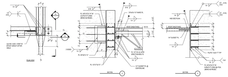
A structural steel strut connection ties into concrete elements using a combination of knife plates, gusset plates, and welded connections. The assembly features a three-eighths-inch by ten-inch by one-foot-four-inch plate with three five-foot-long number seven reinforcing bars, and a half-inch plate secured with two three-quarter-inch diameter erection bolts. Additional support is provided by a seven-eighths-inch by six-inch by one-foot-zero-inch knife plate welded with one-quarter-inch low-hydrogen fillets. Four-by-four W2.1 by W2.1 welded wire fabric is embedded with epoxy grout following the welding operations. Continuous fillet welds of one-quarter-inch and five-sixteenths-inch sizes tie the steel plates and structural members together per the plan specifications.
6" 6" 3" 3" 6" PL 3/4"xt"x2'-0" W/ 8-#5x5'-0" LONG @ 4"GA. (BEND AS REQD) 1/4 TYP 1/4 LO HYD (TYP) 1/4 3 SIDES H SECTION G SECTION 4 1/2" HSS SEE PLAN ROOF SHEATHING 1/4" GUSSET PL 1/4 1/4 4x4-W2.1xW2.1 WWF W/ EPOXY GROUT AFTER WELD 4" 10" 3" 4" 1/4 LO HYD H - G - PLATE 1/2x0'-7" TYP 2" 8" PL 1/2"x7"x2'-0" PL 3/8"x8"x1'-2" PL 3/8"x10"x1'-4" W/ (3) #7x5'-0" LONG (BEND AS REQD) 2" 6" 6" 2" 5/16 4 1/2" 7 1/2" PL 1/2" W/ (2) 3/4"Ø ERECTION BOLTS 7/8"x6"x1'-0" KNIFE PL ROOF SHEATHING 1/2" GUSSET PL @ CENTERLINE 5" SEAT 2" 5/16 1/4 1/4 B.O.S. CL CL PLAN VIEW CL LO HYD (TYP)
Members view this detail in full resolution, download the CAD files (SVG, PDF), and can adapt it in the built-in CAD editor — export DXF, DWG, or PDF.
Start membership