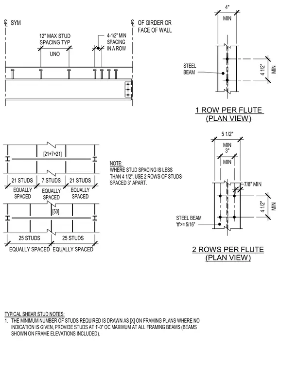
Welded shear stud layouts on steel beams in plan and elevation views. Shear studs are arranged in either one row or two rows per flute depending on flange width and spacing constraints, with a maximum spacing of twelve inches on center unless noted otherwise. When stud spacing is less than four and a half inches, two rows of studs must be provided spaced three inches apart. Flange thickness must be at least five-sixteenths of an inch for two rows per flute configurations. Minimum edge distances and clearances are dimensioned from the centerline of the girder or face of the wall.
[21+7+21] STEEL BEAM 'tf'>= 5/16" [50] 2 ROWS PER FLUTE (PLAN VIEW) 1 ROW PER FLUTE (PLAN VIEW) TYPICAL SHEAR STUD NOTES: 1. THE MINIMUM NUMBER OF STUDS REQUIRED IS DRAWN AS [X] ON FRAMING PLANS WHERE NO INDICATION IS GIVEN, PROVIDE STUDS AT 1'-0" OC MAXIMUM AT ALL FRAMING BEAMS (BEAMS SHOWN ON FRAME ELEVATIONS INCLUDED). EQUALLY SPACED 25 STUDS EQUALLY SPACED 25 STUDS 21 STUDS EQUALLY SPACED 7 STUDS EQUALLY SPACED EQUALLY SPACED 21 STUDS NOTE: WHERE STUD SPACING IS LESS THAN 4 1/2", USE 2 ROWS OF STUDS SPACED 3" APART. MIN 4 1/2" 7/8" MIN MIN 3" MIN 5 1/2" MIN 4 1/2" MIN 4" STEEL BEAM C L SYM C L OF GIRDER OR FACE OF WALL UNO 12" MAX STUD SPACING TYP 4-1/2" MIN. 4-1/2" MIN SPACING IN A ROW
Members view this detail in full resolution, download the CAD files (SVG, PDF), and can adapt it in the built-in CAD editor — export DXF, DWG, or PDF.
Start membership