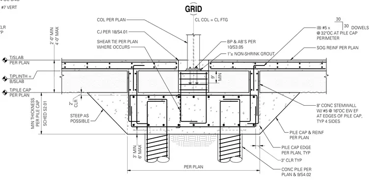
A concrete pile cap supports a column base plate, anchor bolts, and a central plinth. Concrete piles extend into the base with specified clearances, surrounded by pile cap reinforcement and perimeter dowels. An eight-inch concrete stemwall with reinforcing bars frames the edges of the pile cap on all four sides. A layer of non-shrink grout sits beneath the base plate, while the slab-on-grade transitions into the plinth with control joints and shear ties as required.
PILE CAP EDGE PER PLAN, TYP CONC PILE PER PLAN & 9/S4.02 6" MAX 3" MIN PER PLAN STEEP AS POSSIBLE PILE CAP & REINF PER PLAN SCHED S2.01 MIN THICKNESS PER PILE CAP COL PER PLAN 1"± NON-SHRINK GROUT GRID BP & AB'S PER 10/S3.05 CL COL = CL FTG T/PILE CAP PER PLAN SHEAR TIE PER PLAN WHERE OCCURS 4'-0" MAX 2'-0" MIN @ 4"OC UNO TYP 2" CLR (8) #7 VERT T/SLAB PER PLAN T/PLINTH = B/SLAB 3" CLR TYP CJ PER 18/S4.01 MIN 9" CLR 2" (8) #5 x DOWELS @ 32"OC AT PILE CAP PERIMETER 30 30 SOG REINF PER PLAN 8" CONC STEMWALL W/ #5 @ 16"OC EW EF AT EDGES OF PILE CAP, TYP 4 SIDES
Members view this detail in full resolution, download the CAD files (SVG, PDF), and can adapt it in the built-in CAD editor — export DXF, DWG, or PDF.
Start membership