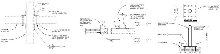
An HSS beam connects to an HSS post using clip angles centered on the HSS, secured with two three-quarter-inch-diameter A325N through bolts spaced one inch from the edge of the angle with typical three-sixteenth-inch welds. A separate support detail features an L4x4x1/4 angle on each side attached with a three-quarter-inch-diameter through bolt centered on the HSS rail support post. A roof tie-off post designed for three thousand one hundred twenty-five pounds ASD design load mounts to a roof panel using a three-quarter-inch by sixteen-inch by one-foot-four-inch plate with twelve three-quarter-inch-diameter by six-inch lag bolts.
ROOF PANEL PL 3/4x16x1'-4" w/ (12) 3/4"Øx6" LAG BOLTS TYP. 2" SPACES (3) EQ. SECTION A-A 3,125 LBS ASD DESIGN LOAD 2' - 0" MAX. TIE-OFF POST BY OTHERS BY OTHERS A A 1 1/2" 1/2" TYP. 1 1/2" TYP. 3" 1/4 PL 1/2x7x0'-10" w/ (4) SDHR31400 ON 3"x8" GRID CENTERED ON HSS HSS RAIL SUPPORT POST WHERE OCCURS REF. PLAN L4x4x1/4 EACH SIDE w/ 3/4" DIA. THRU-BOLT CENTERED ON HSS 3/16 (3/16) TYP. (3/16) (3/16) TYP. HSS BEAM REF. PLAN/ELEVATION HSS POST REF. PLAN TYP. 3/4" GAP MAX. HSS BEAM NOT AT SIM. TYP. 1 1/2" L4x4x5/16x0'-5" CENTERED ON HSS TYP. (2) 3/4"Ø A325N THRU BOLTS SPACED 1" FROM EDGE OF ANGLE TYP. 3/16 3/16 TYP.
Members view this detail in full resolution, download the CAD files (SVG, PDF), and can adapt it in the built-in CAD editor — export DXF, DWG, or PDF.
Start membership