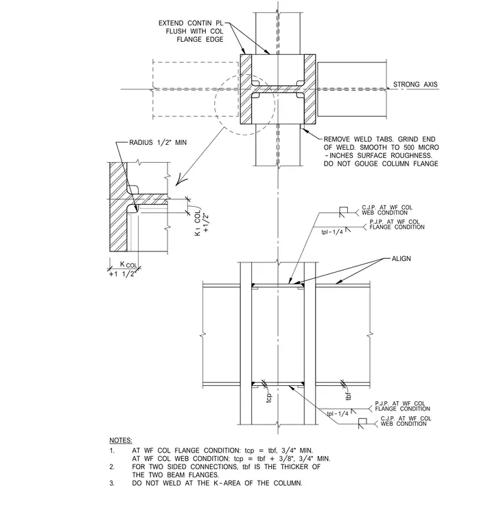
Continuity plates align with the beam flanges on the strong axis of a wide-flange column using complete-joint-penetration welds at the web and partial-joint-penetration welds at the flange. The continuous plates extend flush with the column flange edge. Weld tabs are removed, and the weld ends are ground smooth to a 500 micro-inch surface roughness without gouging the column flange. No welding is permitted within the k-area of the column. Plate thicknesses are sized based on the beam flange thickness, with specific minimum dimensions and edge clearances maintained.
+1/2" K COL 1 +1 1/2" K COL tcp tbf REMOVE WELD TABS. GRIND END OF WELD. SMOOTH TO 500 MICRO -INCHES SURFACE ROUGHNESS. DO NOT GOUGE COLUMN FLANGE EXTEND CONTIN PL FLUSH WITH COL FLANGE EDGE STRONG AXIS RADIUS 1/2" MIN ALIGN FLANGE CONDITION tpl-1/4 P.J.P. AT WF COL NOTES: 1. AT WF COL FLANGE CONDITION: tcp = tbf, 3/4" MIN. AT WF COL WEB CONDITION: tcp = tbf + 3/8", 3/4" MIN. 2. FOR TWO SIDED CONNECTIONS, tbf IS THE THICKER OF THE TWO BEAM FLANGES. 3. DO NOT WELD AT THE K-AREA OF THE COLUMN. WEB CONDITION C.J.P. AT WF COL FLANGE CONDITION tpl-1/4 P.J.P. AT WF COL WEB CONDITION C.J.P. AT WF COL
Members view this detail in full resolution, download the CAD files (SVG, PDF), and can adapt it in the built-in CAD editor — export DXF, DWG, or PDF.
Start membership