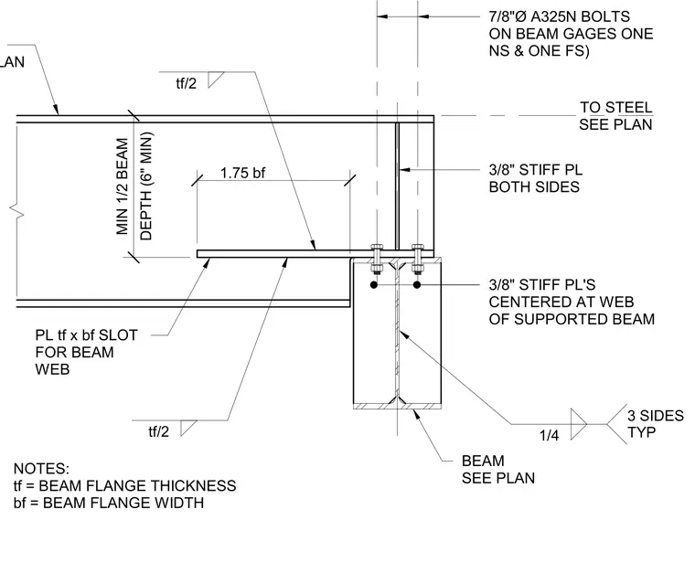
A supported steel beam frames into a supporting steel beam via a seated connection. The supported beam features a slotted web to accommodate the beam flange thickness and width dimensions. Three-eighths-inch thick stiffener plates are welded to both sides and centered at the web of the supported beam. Seven-eighths-inch diameter A325-N bolts on beam gauges connect the assembly, with one near-side and one far-side bolt. Three-eighths-inch stiffener plates are also provided on both sides of the support. Fillet welds of one-quarter-inch size are applied on three sides typically.
NOTES: tf = BEAM FLANGE THICKNESS bf = BEAM FLANGE WIDTH PL tf x bf SLOT FOR BEAM WEB BEAM SEE PLAN TO STEEL SEE PLAN SEE PLAN 3/8" STIFF PL'S CENTERED AT WEB OF SUPPORTED BEAM 3/8" STIFF PL BOTH SIDES 7/8"Ø A325N BOLTS ON BEAM GAGES ONE NS & ONE FS) 1.75 bf tf/2 DEPTH (6" MIN) MIN 1/2 BEAM 1/4 3 SIDES TYP tf/2
Members view this detail in full resolution, download the CAD files (SVG, PDF), and can adapt it in the built-in CAD editor — export DXF, DWG, or PDF.
Start membership