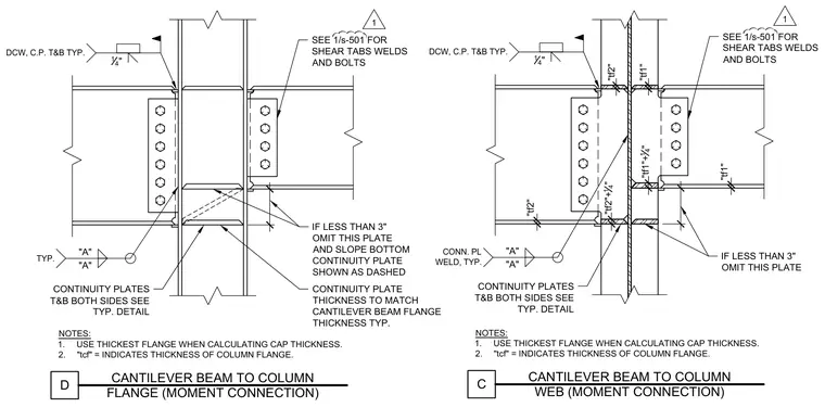
These structural steel details illustrate cantilever beam-to-column moment connections at both the column flange and column web. Beams frame into the column with top and bottom flange moment welds flanked by continuity plates on both sides of the column web. Shear connections use bolted single-plate shear tabs welded to the column face, referencing sheet 1/S-501 for specific weld and bolt sizes. Notes instruct the builder to use the thickest flange when calculating cap thickness, where tcf indicates the thickness of the column flange. Additional notes specify that if dimension A is less than 3 inches, the plate is omitted and the bottom continuity plate is sloped as shown.
NOTES: 1. USE THICKEST FLANGE WHEN CALCULATING CAP THICKNESS. 2. "tcf" = INDICATES THICKNESS OF COLUMN FLANGE. C CANTILEVER BEAM TO COLUMN WEB (MOMENT CONNECTION) "tf1" "tf1"+ 14 " "tf1" "tf2" "tf2"+ 14 " DCW, C.P. T&B TYP. 14 " CONN. PL WELD, TYP. "A" "A" IF LESS THAN 3" OMIT THIS PLATE CONTINUITY PLATES T&B BOTH SIDES SEE TYP. DETAIL SEE 1/s-501 FOR SHEAR TABS WELDS AND BOLTS NOTES: 1. USE THICKEST FLANGE WHEN CALCULATING CAP THICKNESS. 2. "tcf" = INDICATES THICKNESS OF COLUMN FLANGE. D CANTILEVER BEAM TO COLUMN FLANGE (MOMENT CONNECTION) DCW, C.P. T&B TYP. 14 " TYP. "A" "A" IF LESS THAN 3" OMIT THIS PLATE AND SLOPE BOTTOM CONTINUITY PLATE SHOWN AS DASHED CONTINUITY PLATES T&B BOTH SIDES SEE TYP. DETAIL SEE 1/s-501 FOR SHEAR TABS WELDS AND BOLTS "tf2" CONTINUITY PLATE THICKNESS TO MATCH CANTILEVER BEAM FLANGE THICKNESS TYP. 1 1
Members view this detail in full resolution, download the CAD files (SVG, PDF), and can adapt it in the built-in CAD editor — export DXF, DWG, or PDF.
Start membership