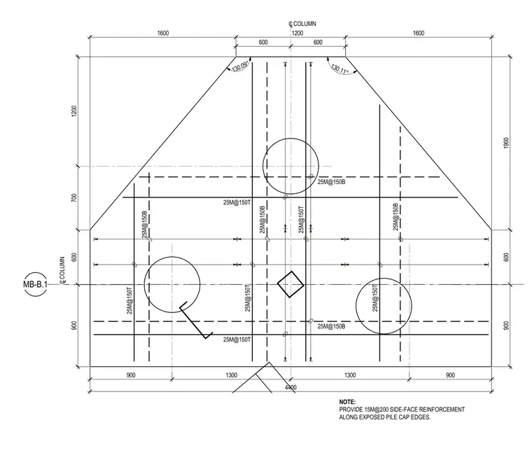
This structural plan details a concrete pile cap measuring 4400 millimeters wide with multiple pile locations centered along column gridlines. The top and bottom mats utilize 25M reinforcing bars spaced at 150 millimeters throughout the assembly. Side-face reinforcement consisting of 15M bars at 200 millimeter spacing is specified along all exposed pile cap edges. The drawing provides comprehensive dimensional layout coordinates and centerline references for column and pile interfaces.
CLCOLUMN CLCOLUMN 25M@150T 25M@150B 25M@150T 25M@150B 25M@150T 25M@150B 25M@150T 25M@150B 25M@150T 25M@150B 25M@150T MB-B.1 NOTE: PROVIDE 15M@200 SIDE-FACE REINFORCEMENT ALONG EXPOSED PILE CAP EDGES. 900 1300 1300 900 4400 900 600 700 1200 900 600 1900 600 600 1600 1200 1600 130.11° 130.09°
Members view this detail in full resolution, download the CAD files (SVG, PDF), and can adapt it in the built-in CAD editor — export DXF, DWG, or PDF.
Start membership