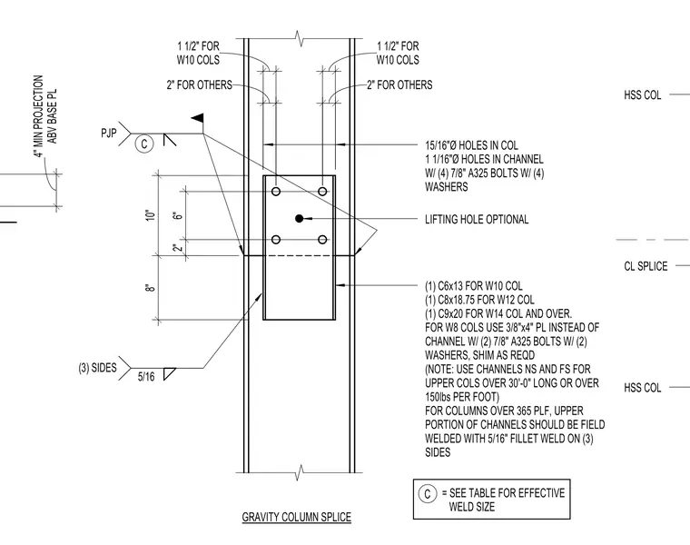
A gravity column splice connects upper and lower steel wide-flange columns with channel splices on near and far sides. The connection utilizes channel sizes ranging from C6x13 for W10 columns up to C9x20 for W14 columns and larger, secured with four seven-eighths inch diameter A325 bolts and washers in matched holes. For W8 columns, a three-eighths by four-inch plate replaces the channel with two seven-eighths inch A325 bolts and shims as required. Columns over 365 pounds per foot require the upper portion of the channels to be field welded with a five-sixteenths inch fillet weld on three sides. A partial joint penetration weld is specified at the column interface with an effective size determined by schedule table reference 'C'. An optional lifting hole is centered on the splice channel plate.
ABV BASE PL 4" MIN PROJECTION 8" 10" 2" 6" 2" FOR OTHERS W10 COLS 1 1/2" FOR 15/16"Ø HOLES IN COL 1 1/16"Ø HOLES IN CHANNEL W/ (4) 7/8" A325 BOLTS W/ (4) WASHERS LIFTING HOLE OPTIONAL (1) C6x13 FOR W10 COL (1) C8x18.75 FOR W12 COL (1) C9x20 FOR W14 COL AND OVER. FOR W8 COLS USE 3/8"x4" PL INSTEAD OF CHANNEL W/ (2) 7/8" A325 BOLTS W/ (2) WASHERS, SHIM AS REQD (NOTE: USE CHANNELS NS AND FS FOR UPPER COLS OVER 30'-0" LONG OR OVER 150lbs PER FOOT) FOR COLUMNS OVER 365 PLF, UPPER PORTION OF CHANNELS SHOULD BE FIELD WELDED WITH 5/16" FILLET WELD ON (3) SIDES GRAVITY COLUMN SPLICE C = SEE TABLE FOR EFFECTIVE WELD SIZE C HSS COL HSS COL CL SPLICE 2" FOR OTHERS W10 COLS 1 1/2" FOR 5/16 (3) SIDES PJP
Members view this detail in full resolution, download the CAD files (SVG, PDF), and can adapt it in the built-in CAD editor — export DXF, DWG, or PDF.
Start membership