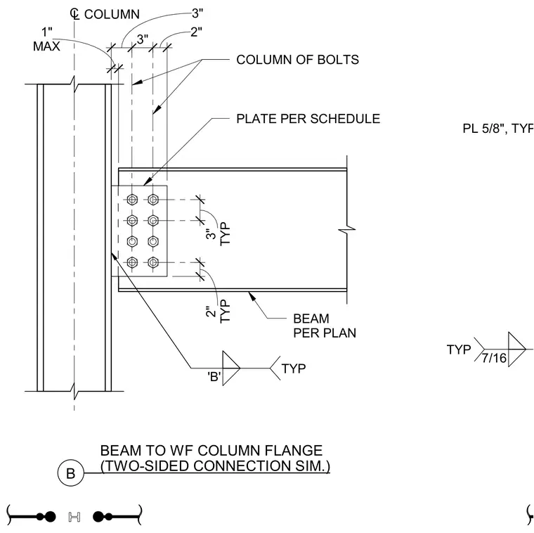
A beam frames into a wide flange column flange using a bolted plate connection. The framing beam per plan connects to the column flange via a five-eighths-inch thick plate sized per schedule, secured with a vertical column of bolts spaced at three inches typical with a two-inch typical edge distance and a maximum one-inch clearance from the column centerline. Fillet welds of seven-sixteenths-inch typical size secure the plate to the supporting column. A two-sided connection is shown symmetrically.
__ __ B (TWO-SIDED CONNECTION SIM.) BEAM TO WF COLUMN FLANGE 3" 3" 2" TYP 3" COLUMN OF BOLTS BEAM PER PLAN TYP 2" 'B' TYP PL 5/8", TYP 7/16 TYP PLATE PER SCHEDULE C L COLUMN MAX 1"
Members view this detail in full resolution, download the CAD files (SVG, PDF), and can adapt it in the built-in CAD editor — export DXF, DWG, or PDF.
Start membership