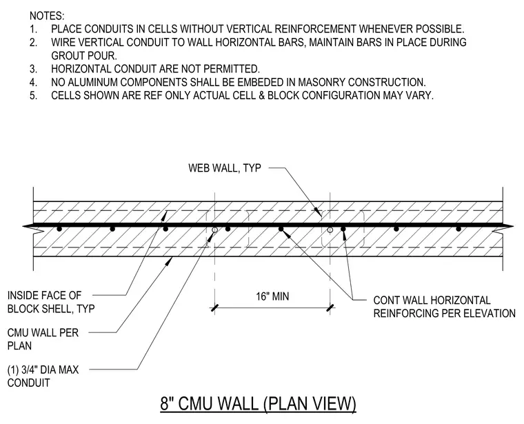
An eight-inch concrete masonry unit wall plan view details horizontal reinforcing bars and single three-quarter-inch maximum diameter conduit placement within block cells. Vertical conduits are positioned in cells lacking vertical reinforcement wherever possible and wired to continuous horizontal bars to maintain alignment during grout pours. Horizontal conduits are prohibited, and aluminum components are excluded from masonry construction to prevent galvanic corrosion. Block cell configurations shown serve as a reference and actual block geometry may vary.
8" CMU WALL (PLAN VIEW) CONT WALL HORIZONTAL REINFORCING PER ELEVATION CMU WALL PER PLAN 16" MIN (1) 3/4" DIA MAX CONDUIT 1. 2. 3. 4. 5. NOTES: PLACE CONDUITS IN CELLS WITHOUT VERTICAL REINFORCEMENT WHENEVER POSSIBLE. WIRE VERTICAL CONDUIT TO WALL HORIZONTAL BARS, MAINTAIN BARS IN PLACE DURING GROUT POUR. HORIZONTAL CONDUIT ARE NOT PERMITTED. NO ALUMINUM COMPONENTS SHALL BE EMBEDED IN MASONRY CONSTRUCTION. CELLS SHOWN ARE REF ONLY ACTUAL CELL & BLOCK CONFIGURATION MAY VARY. INSIDE FACE OF BLOCK SHELL, TYP WEB WALL, TYP
Members view this detail in full resolution, download the CAD files (SVG, PDF), and can adapt it in the built-in CAD editor — export DXF, DWG, or PDF.
Start membership