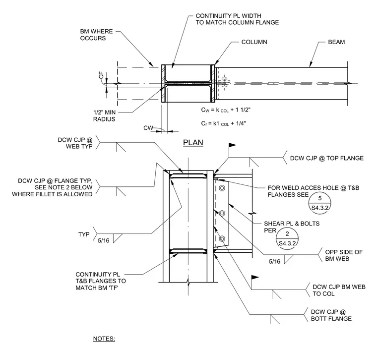
Continuity plates are aligned with the top and bottom flanges of the beam and welded inside the steel column web. The continuity plate width matches the column flange, and plate dimensions are sized based on column properties plus specified clearances. Complete joint penetration welds connect the beam web and flanges to the column, complemented by a shear plate and bolts. Fillet welds of five-sixteenths inch size are applied at the web connection on opposite sides. A one-half inch minimum radius is required at the beam where it occurs for the weld access hole.
PLAN COLUMN BEAM CONTINUITY PL T&B FLANGES TO MATCH BM 'TF' CONTINUITY PL WIDTH TO MATCH COLUMN FLANGE NOTES: 1/2" MIN RADIUS BM WHERE OCCURS FOR WELD ACCES HOLE @ T&B FLANGES SEE SHEAR PL & BOLTS PER C f = k1 COL + 1/4" C W = k COL + 1 1/2" 2 S4.3.2 CF CW DCW CJP @ WEB TYP DCW CJP @ FLANGE TYP, SEE NOTE 2 BELOW WHERE FILLET IS ALLOWED 5/16 TYP DCW CJP @ TOP FLANGE 5/16 OPP SIDE OF BM WEB DCW CJP @ BOTT FLANGE DCW CJP BM WEB TO COL 5 S4.3.2
Members view this detail in full resolution, download the CAD files (SVG, PDF), and can adapt it in the built-in CAD editor — export DXF, DWG, or PDF.
Start membership