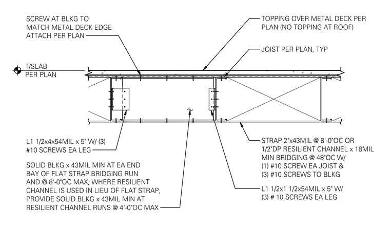
Cold-formed steel joist bridging and solid blocking configurations occur beneath a metal deck and floor slab. A solid blocking member fabricated from forty-three mil minimum steel is required at each end bay of flat strap bridging runs at eight feet on center maximum, or at four feet on center maximum where resilient channel is used instead of flat strap. The bridging consists of either a two-inch by forty-three mil strap spaced at eight feet on center or a one-half-inch deep resilient channel by eighteen mil minimum spaced at forty-eight inches on center, secured to each joist with one number ten screw and to the blocking with three number ten screws. Angle clips measuring one-and-one-half by one-and-one-half by fifty-four mil by five inches or one-and-one-half by four by fifty-four mil by five inches attach the components using three number ten screws per leg. Screws at the blocking match the metal deck edge attachment specified in the structural plans.
SCREW AT BLKG TO MATCH METAL DECK EDGE ATTACH PER PLAN SOLID BLKG x 43MIL MIN AT EA END BAY OF FLAT STRAP BRIDGING RUN AND @ 8'-0"OC MAX, WHERE RESILIENT CHANNEL IS USED IN LIEU OF FLAT STRAP, PROVIDE SOLID BLKG x 43MIL MIN AT RESILIENT CHANNEL RUNS @ 4'-0"OC MAX TOPPING OVER METAL DECK PER PLAN (NO TOPPING AT ROOF) JOIST PER PLAN, TYP STRAP 2"x43MIL @ 8'-0"OC OR 1/2"DP RESILIENT CHANNEL x 18MIL MIN BRIDGING @ 48"OC W/ (1) #10 SCREW EA JOIST & (3) #10 SCREWS TO BLKG L1 1/2x1 1/2x54MIL x 5" W/ (3) # 10 SCREWS EA LEG L1 1/2x4x54MIL x 5" W/ (3) #10 SCREWS EA LEG T/SLAB PER PLAN
Members view this detail in full resolution, download the CAD files (SVG, PDF), and can adapt it in the built-in CAD editor — export DXF, DWG, or PDF.
Start membership