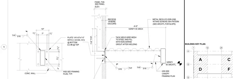
A hollow structural section canopy member connects to a concrete wall via a quarter-inch by ten-inch by one-foot plate secured with three-quarter-inch diameter welded studs at the bottom and number six reinforcing bars at the top. A metal deck is attached with tack screws in a thirty-six-four pattern and features a four-foot dimension verified with the architect. Wire mesh is tack-welded to the steel and the assembly is filled with non-shrink grout after welding, with typical three-sixteenth-inch fillet welds specified throughout. The concrete wall includes a recessed pocket matching the panel thickness shown in the panel elevation. A building key plan is included on the right to reference structural grid lines A through Q and 1 through 25.
1'-6" TYP. METAL DECK ICC-ESR-2385 VERIFY W/ ARCHT'L. WITH 2- 3/4 DIA. W.S. PLATE 1/4"x10"x1'-0" 4'-0" VERIFY W/ ARCH TYP 3/16 HSS SEE CANOPY SEE PANEL PANEL THK. ELEV. RECESS WHERE OCCURS W/TAKS SCREWS 36/4 PATERN (SEE ARCHT'L FOR SLOPE) TACK WELD WIRE MESH TO STEEL AND FILL WITH NON-SHRINK GROUT AFTER WELDING TYP 3/16 & 2-#6 @ TOP @ BOTTOM FRAMING PLAN TYP 10" HSS SEE FRAMING PLAN, TYP. 1 1 /2 " 1 1 /2 " CONC. WALL 1 1/2 " 4" 7" 3/16 7 1/2 " 1 BUILDING KEY PLAN: 12 G A Q 1 25 A D F C
Members view this detail in full resolution, download the CAD files (SVG, PDF), and can adapt it in the built-in CAD editor — export DXF, DWG, or PDF.
Start membership