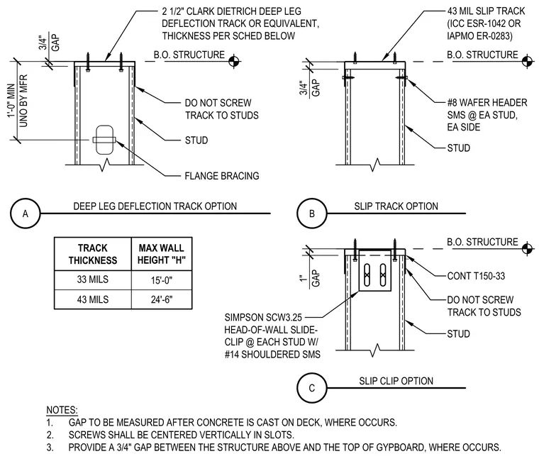
Three alternative head-of-wall connection details illustrate methods for accommodating vertical deflection between cold-formed steel framing and the structure above. Option A features a two-and-a-half-inch Clark Dietrich deep leg deflection track with flange bracing, leaving the track left unwelded and unscrewed to the studs to allow vertical movement with a three-quarter-inch gap. Option B utilizes a forty-three mil slip track secured with number eight wafer header sheet metal screws at each stud on each side. Option C employs a Simpson SCW three-point-twenty-five head-of-wall slide clip at each stud with number fourteen shouldered sheet metal screws centered vertically in the slots. A thickness schedule provides maximum wall heights of fifteen feet for thirty-three mil tracks and twenty-four feet six inches for forty-three mil tracks. General notes require gaps to be measured after concrete casting on deck and specify a three-quarter-inch gap between the structure above and the top of the gypsum board.
3/4" GAP 1'-0" MIN UNO BY MFR 3/4" GAP 1" GAP 2 1/2" CLARK DIETRICH DEEP LEG DEFLECTION TRACK OR EQUIVALENT, THICKNESS PER SCHED BELOW DO NOT SCREW TRACK TO STUDS FLANGE BRACING 43 MIL SLIP TRACK (ICC ESR-1042 OR IAPMO ER-0283) #8 WAFER HEADER SMS @ EA STUD, EA SIDE DO NOT SCREW TRACK TO STUDS CONT T150-33 STUD SIMPSON SCW3.25 HEAD-OF-WALL SLIDE- CLIP @ EACH STUD W/ #14 SHOULDERED SMS TRACK THICKNESS MAX WALL HEIGHT "H" 33 MILS 15'-0" 43 MILS 24'-6" NOTES: 1. GAP TO BE MEASURED AFTER CONCRETE IS CAST ON DECK, WHERE OCCURS. 2. SCREWS SHALL BE CENTERED VERTICALLY IN SLOTS. 3. PROVIDE A 3/4" GAP BETWEEN THE STRUCTURE ABOVE AND THE TOP OF GYPBOARD, WHERE OCCURS. STUD B.O. STRUCTURE B.O. STRUCTURE STUD B.O. STRUCTURE A DEEP LEG DEFLECTION TRACK OPTION B SLIP TRACK OPTION C SLIP CLIP OPTION
Members view this detail in full resolution, download the CAD files (SVG, PDF), and can adapt it in the built-in CAD editor — export DXF, DWG, or PDF.
Start membership