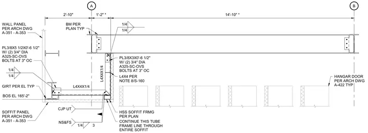
The framing connection for a hangar door soffit runs between grid lines A and B. A horizontal steel beam connects to framing members with a three-eighths-inch by three-inch by six-and-a-half-inch plate secured by two three-quarter-inch diameter A325-SC-OVS bolts spaced at three inches on center, supplemented by welded connections. Additional support is provided by L4x4 angles and a three-eighths-inch by five-and-a-half-inch by six-and-a-half-inch connection plate with matching bolt assemblies. Wall panels, soffit panels, and hangar doors interface with the assembly per architectural drawings, while bottom of steel elevation is established at 165'-2".
A B 2'-10" 1'-2" * 14'-10" * GIRT PER EL TYP BOS EL 165'-2" 1/4 1/4 PL3/8X3X0'-6 1/2" W/ (2) 3/4" DIA A325-SC-OVS BOLTS AT 3" OC L4X4 PER NOTE 8/S-160 S-160 1/4 1/4 1/4 3 NS&FS CJP UT HSS SOFFIT FRMG PER PLAN L4X4X1/4 L4X4X1/4 PL3/8X5 1/2X0'-6 1/2" W/ (2) 3/4" DIA A325-SC-OVS BOLTS AT 3" OC WALL PANEL PER ARCH DWG A-351 - A-353 HANGAR DOOR PER ARCH DWG A-422 TYP SOFFIT PANEL PER ARCH DWG A-351 - A-353 CONTINUE THIS TUBE FRAME LINE THROUGH ENTIRE SOFFIT BM PER PLAN TYP
Members view this detail in full resolution, download the CAD files (SVG, PDF), and can adapt it in the built-in CAD editor — export DXF, DWG, or PDF.
Start membership