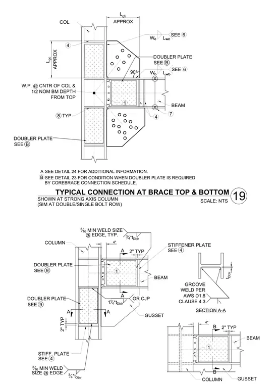
A typical braced frame connection occurs at the top and bottom of a brace meeting a column and beam intersection on the strong axis of the column. The working point is located at the center of the column and one-half of the nominal beam depth from the top. A gusset plate connects the brace to the column and beam flange, secured with bolted connections and perimeter welds. Stiffener plates are welded to the beam web with typical three-sixteenths inch minimum edge welds. Doubler plates are provided at the column web as required by the connection schedule, utilizing complete joint penetration groove welds per AWS D1.8 Clause 4.3.
L gc APPROX COL 4 W.P. @ CNTR OF COL & 1/2 NOM BM DEPTH FROM TOP L gb APPROX 4 6 SEE W b BEAM 90° 6 SEE W c 1 X X 7 L wc L wb 8 TYP TYPICAL CONNECTION AT BRACE TOP & BOTTOM SCALE: NTS SHOWN AT STRONG AXIS COLUMN (SIM AT DOUBLE/SINGLE BOLT ROW) SEE DETAIL 23 FOR CONDITION WHEN DOUBLER PLATE IS REQUIRED BY COREBRACE CONNECTION SCHEDULE. SEE DETAIL 24 FOR ADDITIONAL INFORMATION. B DOUBLER PLATE B SEE DOUBLER PLATE B SEE A 19 OR CJP DOUBLER PLATE GROOVE WELD PER AWS D1.8 CLAUSE 4.3 t Dblr COLUMN A A SECTION A-A 1 14 *t Dblr 2" TYP STIFF. PLATE 4 SEE BEAM A A 3 4 *t Dblr 316 MIN WELD SIZE @ EDGE, TYP. 4" 2" TYP STIFFENER PLATE 4 SEE 1 BEAM COLUMN B B 4" 2" TYP 1 3 4 *t Dblr 316 MIN WELD SIZE @ EDGE 9 SEE DOUBLER PLATE 9 SEE GUSSET GUSSET
Members view this detail in full resolution, download the CAD files (SVG, PDF), and can adapt it in the built-in CAD editor — export DXF, DWG, or PDF.
Start membership