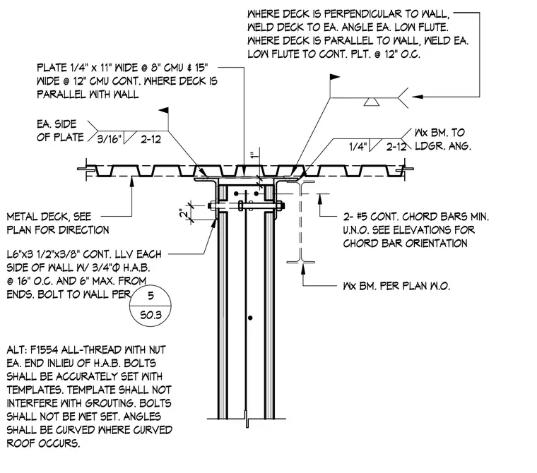
A metal roof deck connects to a concrete masonry unit wall via continuous L6x3 1/2x3/8 ledger angles on each side of the wall secured with 3/4-inch diameter head anchor bolts spaced at 16 inches on center. A continuous 1/4-inch plate is provided at parallel deck conditions, while perpendicular deck conditions weld directly to the ledger angles at each low flute. Two continuous number 5 chord bars are embedded in the wall minimum unless noted otherwise. A wide-flange beam connects to the ledger angle with a 1/4-inch fillet weld.
L6"x3 1/2"x3/8" CONT. LLV EACH SIDE OF WALL W/ 3/4"Ø H.A.B. @ 16" O.C. AND 6" MAX. FROM ENDS. BOLT TO WALL PER Wx BM. PER PLAN W.O. 2- #5 CONT. CHORD BARS MIN. U.N.O. SEE ELEVATIONS FOR CHORD BAR ORIENTATION METAL DECK, SEE PLAN FOR DIRECTION ALT: F1554 ALL-THREAD WITH NUT EA. END INLIEU OF H.A.B. BOLTS SHALL BE ACCURATELY SET WITH TEMPLATES. TEMPLATE SHALL NOT INTERFERE WITH GROUTING. BOLTS SHALL NOT BE WET SET. ANGLES SHALL BE CURVED WHERE CURVED ROOF OCCURS. 1/4" 2-12 1" Wx BM. TO LDGR. ANG. WHERE DECK IS PERPENDICULAR TO WALL, WELD DECK TO EA. ANGLE EA. LOW FLUTE. WHERE DECK IS PARALLEL TO WALL, WELD EA. LOW FLUTE TO CONT. PLT. @ 12" O.C. 3/16" 2-12 EA. SIDE OF PLATE PLATE 1/4" x 11" WIDE @ 8" CMU & 15" WIDE @ 12" CMU CONT. WHERE DECK IS PARALLEL WITH WALL 5 S0.3 2"
Members view this detail in full resolution, download the CAD files (SVG, PDF), and can adapt it in the built-in CAD editor — export DXF, DWG, or PDF.
Start membership