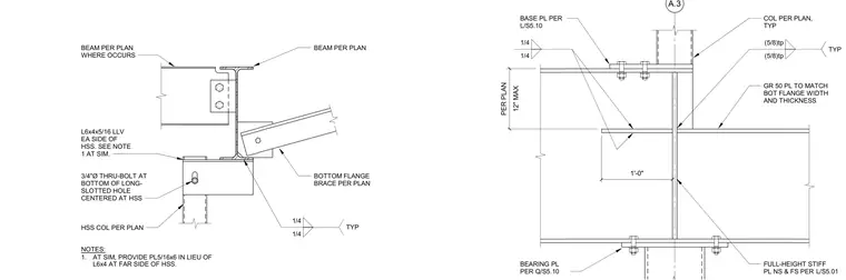
This structural detail shows a beam framing into a hollow structural section column with a bottom flange brace secured by a three-quarter-inch diameter thru-bolt positioned in a long-slotted hole. An angle section is attached to each side of the hollow structural section, with a five-sixteenth-inch plate provided at the far side on similar conditions. Full-height stiffener plates are welded to the near side and far side of the column web with quarter-inch fillet welds. A grade fifty bearing plate matches the bottom flange width and thickness, connected with base plates sized per plan. A twelve-inch maximum dimension governs the vertical spacing of the brace attachment.
1'-0" GR 50 PL TO MATCH BOT FLANGE WIDTH AND THICKNESS BEARING PL PER BASE PL PER 12" MAX PER PLAN L/S5.10 Q/S5.10 1/4 1/4 COL PER PLAN, TYP (5/8)tp (5/8)tp TYP FULL-HEIGHT STIFF PL NS & FS PER L/S5.01 3/4"Ø THRU-BOLT AT BOTTOM OF LONG- SLOTTED HOLE CENTERED AT HSS BOTTOM FLANGE BRACE PER PLAN HSS COL PER PLAN L6x4x5/16 LLV EA SIDE OF HSS. SEE NOTE 1 AT SIM. BEAM PER PLAN 1/4 1/4 TYP BEAM PER PLAN WHERE OCCURS NOTES: 1. AT SIM, PROVIDE PL5/16x6 IN LIEU OF L6x4 AT FAR SIDE OF HSS.
Members view this detail in full resolution, download the CAD files (SVG, PDF), and can adapt it in the built-in CAD editor — export DXF, DWG, or PDF.
Start membership