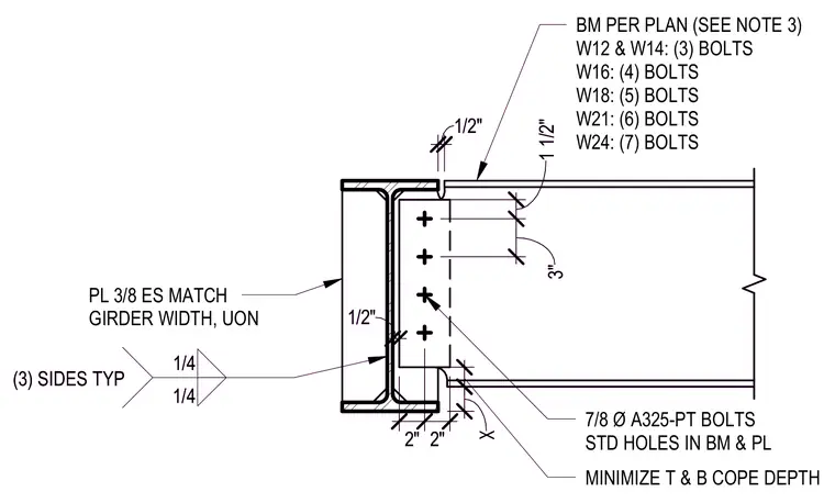
A standard framing connection between a steel beam and a supporting girder web uses a bolted shear plate. A three-eighths-inch thick plate, sized to match the girder width unless otherwise noted, is welded to the supporting girder web with quarter-inch fillet welds on three sides typically. The supported beam features minimized top and bottom flange copes with a half-inch clearance from the support face. Seven-eighths-inch diameter ASTM A325-PT bolts in standard holes connect the beam web to the plate, with bolt counts varying from three to seven depending on the beam depth ranging from W12 to W24 sections.
7/8 Ø A325-PT BOLTS STD HOLES IN BM & PL BM PER PLAN (SEE NOTE 3) W12 & W14: (3) BOLTS W16: (4) BOLTS W18: (5) BOLTS W21: (6) BOLTS W24: (7) BOLTS 1/4 1/4 (3) SIDES TYP 1/2" 1 1/2" 3" MINIMIZE T & B COPE DEPTH 1/2" PL 3/8 ES MATCH GIRDER WIDTH, UON 2" 2" X 7/8 Ø A325-PT BOLTS STD HOLES IN BM & PL BM PER PLAN (SEE NOTE 3) W12 & W14: (3) BOLTS W16: (4) BOLTS W18: (5) BOLTS W21: (6) BOLTS W24: (7) BOLTS 1/4 1/4 (3) SIDES TYP 1/2" 1 1/2" 3" MINIMIZE T & B COPE DEPTH 1/2" PL 3/8 ES MATCH GIRDER WIDTH, UON 2" 2" X
Members view this detail in full resolution, download the CAD files (SVG, PDF), and can adapt it in the built-in CAD editor — export DXF, DWG, or PDF.
Start membership