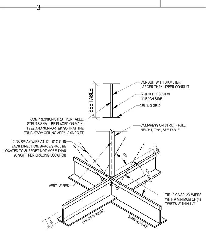
This seismic ceiling bracing detail features twelve-gauge splay wires spaced at twelve feet on center in each direction, anchored to support a maximum tributary area of ninety-six square feet per bracing location. Splay wires are tied with a minimum of four twists within one and a half inches. A full-height compression strut sized per table is positioned at the intersection of the main runner and cross runner. The compression strut is fastened using two number ten Tek screws, with one on each side.
45° 2" MAX 45° MAX 2" MAX CROSS RUNNER MAIN RUNNER COMPRESSION STRUT - FULL HEIGHT, TYP., SEE TABLE TIE 12 GA SPLAY WIRES WITH A MINIMUM OF (4) TWISTS WITHIN 1½" VERT. WIRES CONDUIT WITH DIAMETER LARGER THAN UPPER CONDUIT (2) #10 TEK SCREW (1) EACH SIDE COMPRESSION STRUT PER TABLE. STRUTS SHALL BE PLACED ON MAIN- TEES AND SUPPORTED SO THAT THE TRUBUTARY CEILING AREA IS 96 SQ FT SEE TABLE CEILING GRID 12 GA SPLAY WIRE AT 12' - 0" O.C. IN EACH DIRECTION. BRACE SHALL BE LOCATED TO SUPPORT NOT MORE THAN 96 SQ FT PER BRACING LOCATION 3
Members view this detail in full resolution, download the CAD files (SVG, PDF), and can adapt it in the built-in CAD editor — export DXF, DWG, or PDF.
Start membership