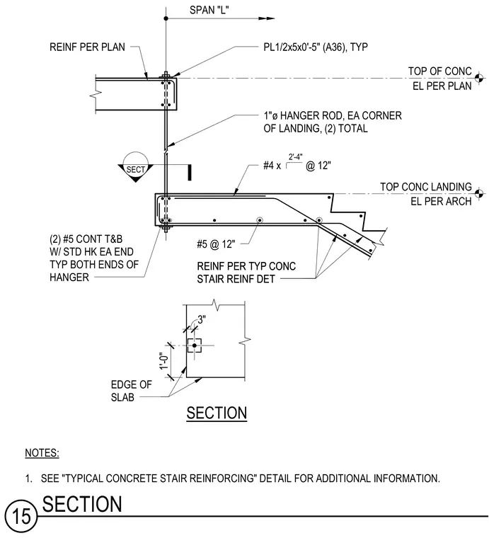
A concrete stair landing is suspended from the structural slab above using one-inch diameter steel hanger rods located at each corner of the landing, totaling two rods. The upper end of each hanger rod anchors through a half-inch by five-inch by five-inch A36 steel plate bearing on the top of the slab. The lower end anchors into the concrete landing slab with two continuous number five top and bottom reinforcing bars featuring standard hooks at each end. Additional reinforcement includes number five bars at twelve inches on center and number four bars shaped as hooks at twelve inches on center. The landing connects back to the main concrete stair run with standard stair reinforcing details per plan.
SECT SPAN "L" REINF PER TYP CONC STAIR REINF DET REINF PER TYP CONC STAIR REINF DET NOTES: 1. SEE "TYPICAL CONCRETE STAIR REINFORCING" DETAIL FOR ADDITIONAL INFORMATION. SECTION 3" 1'-0" EDGE OF SLAB EL PER PLAN TOP OF CONC EL PER ARCH TOP CONC LANDING #5 @ 12" #4 x @ 12" 2'-4" 1"ø HANGER ROD, EA CORNER OF LANDING, (2) TOTAL PL1/2x5x0'-5" (A36), TYP REINF PER PLAN (2) #5 CONT T&B W/ STD HK EA END TYP BOTH ENDS OF HANGER 15 SECTION
Members view this detail in full resolution, download the CAD files (SVG, PDF), and can adapt it in the built-in CAD editor — export DXF, DWG, or PDF.
Start membership