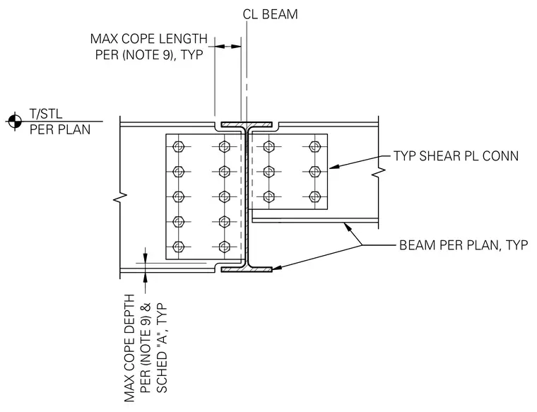
A supported steel beam connects to a supporting steel beam web using a typical shear plate connection with multiple bolts on both sides of the centerline. The top and bottom flanges of the supported beam are coped to clear the supporting beam flanges, maintaining a maximum cope depth and maximum cope length defined by project notes and the beam schedule. The top of steel elevation is located per plan.
TYP SHEAR PL CONN BEAM PER PLAN, TYP CL BEAM SCHED "A", TYP MAX COPE DEPTH PER (NOTE 9) & T/STL PER PLAN PER (NOTE 9), TYP MAX COPE LENGTH
Members view this detail in full resolution, download the CAD files (SVG, PDF), and can adapt it in the built-in CAD editor — export DXF, DWG, or PDF.
Start membership