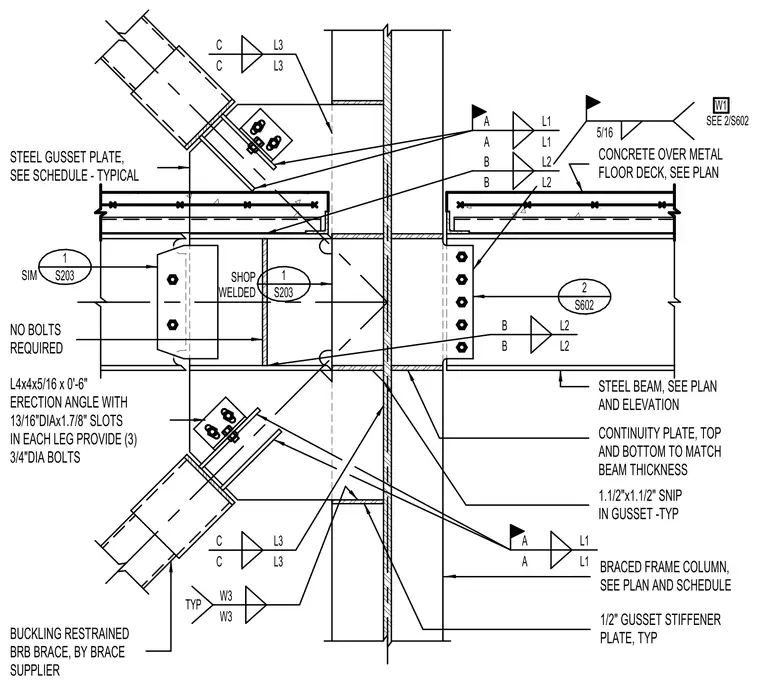
A buckling-restrained brace connects to a shop-welded steel gusset plate welded to the braced frame column and steel floor beam. Continuity plates matching the beam thickness are placed at the top and bottom. An erection angle measuring L4x4x5/16 by zero feet six inches with thirteen-sixteenths inch by one and seven-eighths inch slots in each leg utilizes three three-quarter-inch diameter bolts. A one and one-half inch by one and one-half inch snip is detailed in the gusset plate. A one-half-inch gusset stiffener plate is provided typically.
1 S203 SIM 2 S602 1 S203 SHOP WELDED BRACED FRAME COLUMN, SEE PLAN AND SCHEDULE A A C C B B STEEL GUSSET PLATE, SEE SCHEDULE - TYPICAL A A C C B B CONCRETE OVER METAL FLOOR DECK, SEE PLAN STEEL BEAM, SEE PLAN CONTINUITY PLATE, TOP AND BOTTOM TO MATCH BEAM THICKNESS AND ELEVATION 5/16 L4x4x5/16 x 0'-6" ERECTION ANGLE WITH 13/16"DIAx1.7/8" SLOTS IN EACH LEG PROVIDE (3) 3/4"DIA BOLTS BUCKLING RESTRAINED BRB BRACE, BY BRACE SUPPLIER SEE 2/S602 W1 L3 L3 L2 L2 L2 L2 L3 L3 NO BOLTS REQUIRED 1.1/2"x1.1/2" SNIP IN GUSSET -TYP 1/2" GUSSET STIFFENER PLATE, TYP TYP W3 W3 L1 L1 L1 L1
Members view this detail in full resolution, download the CAD files (SVG, PDF), and can adapt it in the built-in CAD editor — export DXF, DWG, or PDF.
Start membership