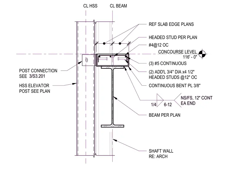
A concrete slab strip sits on a steel beam per plan at the concourse level of 116 feet and 0 inches, featuring three continuous number 5 reinforcing bars and number 4 bars spaced at 12 inches on center. Two additional three-quarter-inch diameter by 4-and-one-half-inch headed studs are welded at 12 inches on center. A continuous 3-eighths-inch bent plate connects the slab assembly to the hollow structural section elevator post. The supporting steel beam incorporates a one-quarter-inch fillet weld at 6 to 12 inches on the near side and far side, continuing continuously at each end. A shaft wall is coordinated per the architectural drawings.
CONCOURSE LEVEL 116' - 0" CL BEAM SHAFT WALL RE: ARCH CONTINUOUS BENT PL 3/8" (3) #5 CONTINUOUS BEAM PER PLAN HEADED STUD PER PLAN REF SLAB EDGE PLANS HSS ELEVATOR POST SEE PLAN CL HSS #4@12 OC (2) ADD'L 3/4" DIA x4 1/2" HEADED STUDS @12" OC 1/4 6-12 NS/FS, 12" CONT EA END POST CONNECTION SEE 3/S3.201 CONCOURSE LEVEL 116' - 0" CL BEAM SHAFT WALL RE: ARCH CONTINUOUS BENT PL 3/8" (3) #5 CONTINUOUS BEAM PER PLAN HEADED STUD PER PLAN REF SLAB EDGE PLANS HSS ELEVATOR POST SEE PLAN CL HSS #4@12 OC (2) ADD'L 3/4" DIA x4 1/2" HEADED STUDS @12" OC 1/4 6-12 NS/FS, 12" CONT EA END POST CONNECTION SEE 3/S3.201
Members view this detail in full resolution, download the CAD files (SVG, PDF), and can adapt it in the built-in CAD editor — export DXF, DWG, or PDF.
Start membership