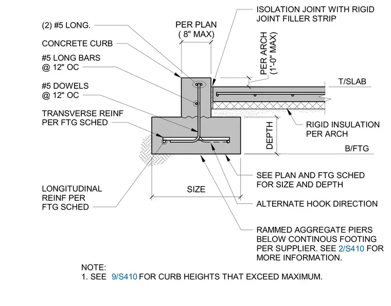
A continuous concrete footing is reinforced with transverse and longitudinal reinforcing bars sized per the footing schedule, featuring alternate hook directions. Number 5 dowels spaced at twelve inches on center extend vertically from the footing into a poured concrete curb containing two number five longitudinal bars and number five long bars at twelve inches on center. The adjacent concrete slab-on-grade bears at the top of the slab elevation, separated from the concrete curb by an isolation joint with a rigid joint filler strip. Rigid insulation per the architectural drawings is placed beneath the slab. Rammed aggregate piers are installed below the continuous footing per the supplier specifications.
B/FTG T/SLAB SEE PLAN AND FTG SCHED FOR SIZE AND DEPTH ALTERNATE HOOK DIRECTION DEPTH SIZE #5 DOWELS @ 12" OC LONGITUDINAL REINF PER FTG SCHED TRANSVERSE REINF PER FTG SCHED RAMMED AGGREGATE PIERS BELOW CONTINOUS FOOTING PER SUPPLIER. SEE 2/S410 FOR MORE INFORMATION. (1'-0" MAX) PER ARCH ISOLATION JOINT WITH RIGID JOINT FILLER STRIP CONCRETE CURB (2) #5 LONG. #5 LONG BARS @ 12" OC 2/S410 RIGID INSULATION PER ARCH PER PLAN ( 8" MAX) NOTE: 1. SEE FOR CURB HEIGHTS THAT EXCEED MAXIMUM. 9/S410
Members view this detail in full resolution, download the CAD files (SVG, PDF), and can adapt it in the built-in CAD editor — export DXF, DWG, or PDF.
Start membership