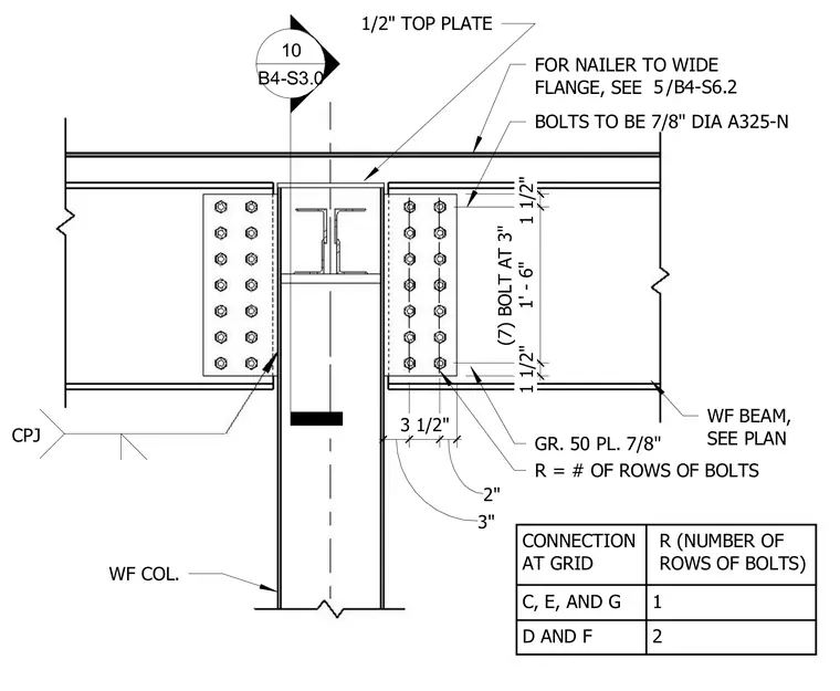
A wide flange beam frames into a wide flange column utilizing a grade fifty seven-eighths inch plate and a one-half inch top plate. Seven-eighths inch diameter A325-N bolts connect the beam webs with spacing set at three inches on center over a total distance of one foot six inches. A connection schedule defines the number of rows of bolts based on the specific grid location. A nailer is detailed above the wide flange beam per plan.
WF BEAM, SEE PLAN FOR NAILER TO WIDE FLANGE, SEE GR. 50 PL. 7/8" 1/2" TOP PLATE WF COL. 1 1/2" (7) BOLT AT 3" 1' - 6" 1 1/2" CPJ 3" 3 1/2" 2" BOLTS TO BE 7/8" DIA A325-N 10 B4-S3.0 R = # OF ROWS OF BOLTS CONNECTION AT GRID R (NUMBER OF ROWS OF BOLTS) C, E, AND G 1 D AND F 2 / 5 B4-S6.2
Members view this detail in full resolution, download the CAD files (SVG, PDF), and can adapt it in the built-in CAD editor — export DXF, DWG, or PDF.
Start membership