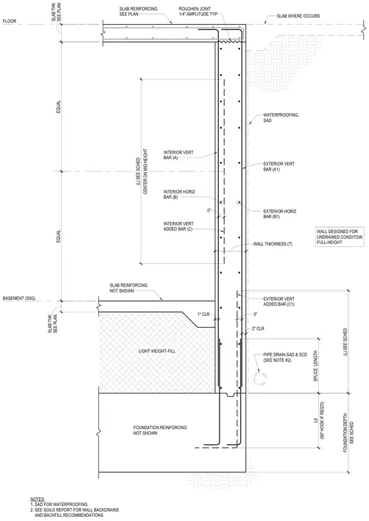
A reinforced concrete basement wall connects to a basement slab on grade and upper floor slab. The wall features exterior and interior vertical and horizontal reinforcing bars with specified lap splice lengths and ninety-degree hooks as required. A roughened construction joint with a one-quarter-inch amplitude is detailed at the top of the wall below the floor slab. Waterproofing is applied to the exterior face, and a pipe drain is located near the base per geotechnical recommendations. The wall is designed for undrained conditions with designated clearance dimensions and lightweight fill beneath the interior slab.
BASEMENT (S0G) FLOOR SLAB WHERE OCCURS EXTERIOR VERT BAR (A1) EXTERIOR HORIZ BAR (B1) EXTERIOR VERT ADDED BAR (C1) PIPE DRAIN SAD & SCD (SEE NOTE #2) INTERIOR VERT ADDED BAR (C) INTERIOR HORIZ BAR (B) INTERIOR VERT BAR (A) SLAB REINFORCING SEE PLAN NOTES: 1. SAD FOR WATERPROOFING. 2. SEE SOILS REPORT FOR WALL BACKDRAINS AND BACKFILL RECOMMENDATIONS. SEE PLAN SLAB THK EQUAL EQUAL WALL THICKNESS (T) 2" CLR SPLICE LENGTH (L) SEE SCHED (90º HOOK IF REQ'D) Ld SEE PLAN SLAB THK SEE SCHED FOUNDATION DEPTH 1" CLR WALL DESIGNED FOR UNDRAINED CONDITOIN FULL-HEIGHT FOUNDATION REINFORCING NOT SHOWN LIGHT WEIGHT-FILL SLAB REINFORCING NOT SHOWN WATERPROOFING, SAD 0" 0" CENTER ON MID HEIGHT (L) SEE SCHED ROUGHEN JOINT 1/4" AMPLITUDE TYP
Members view this detail in full resolution, download the CAD files (SVG, PDF), and can adapt it in the built-in CAD editor — export DXF, DWG, or PDF.
Start membership