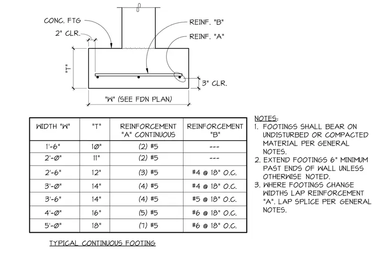
A continuous concrete footing supports a foundation wall, accompanied by a comprehensive sizing schedule. The concrete footing features a variable width "W" and thickness "T" with specified clear cover of two inches at the top and three inches at the bottom. Longitudinal reinforcement "A" is positioned continuously near the bottom with transverse reinforcement "B" spaced at eighteen inches on center. A companion schedule correlates footing widths ranging from one foot six inches to five feet with corresponding thicknesses from ten to eighteen inches, continuous rebar counts from two to seven number five bars, and transverse reinforcing sizes. General notes specify that footings must bear on undisturbed or compacted material, extend six inches minimum past the ends of walls, and lap splice reinforcement where footing widths change.
WIDTH "W" "T" REINFORCEMENT "A" CONTINUOUS REINFORCEMENT "B" 1'-6" 10" (2) #5 --- 2'-0" 11" (2) #5 #4 @ 18" O.C. 2'-6" 12" (3) #5 3'-0" 14" (4) #5 3'-6" 14" (4) #5 4'-0" 16" (5) #5 #4 @ 18" O.C. #5 @ 18" O.C. #6 @ 18" O.C. 5'-0" 18" (7) #5 #6 @ 18" O.C. --- NOTES: 1. FOOTINGS SHALL BEAR ON UNDISTURBED OR COMPACTED MATERIAL PER GENERAL NOTES. 2. EXTEND FOOTINGS 6" MINIMUM PAST ENDS OF WALL UNLESS OTHERWISE NOTED. 3. WHERE FOOTINGS CHANGE WIDTHS LAP REINFORCEMENT "A". LAP SPLICE PER GENERAL NOTES. "W" (SEE FDN PLAN) "T" CONC. FTG REINF. "B" REINF. "A" TYPICAL CONTINUOUS FOOTING 2" CLR. 3" CLR.
Members view this detail in full resolution, download the CAD files (SVG, PDF), and can adapt it in the built-in CAD editor — export DXF, DWG, or PDF.
Start membership