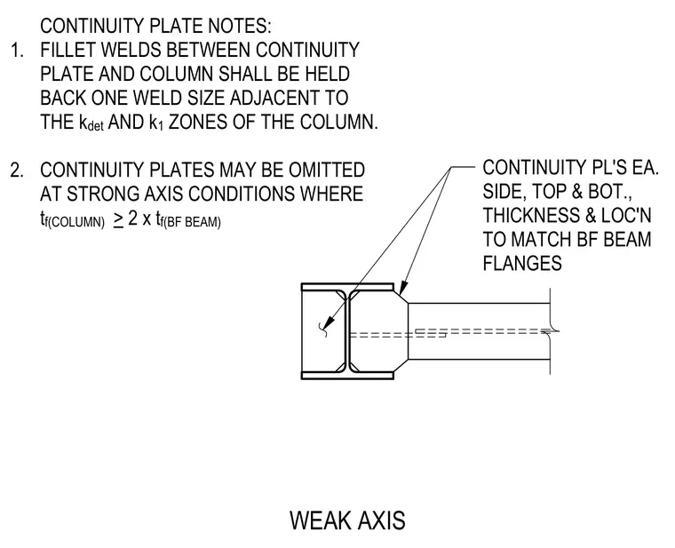
Continuity plates are placed on each side at the top and bottom of the column web, with thickness and location matching the beam flanges. Fillet welds between the continuity plate and the column are held back one weld size adjacent to the kdet and k1 zones of the column. Continuity plates may be omitted at strong axis conditions where the column flange thickness is greater than or equal to two times the beam flange thickness.
CONTINUITY PL'S EA. SIDE, TOP & BOT., THICKNESS & LOC'N TO MATCH BF BEAM FLANGES 1. 2. CONTINUITY PLATE NOTES: FILLET WELDS BETWEEN CONTINUITY PLATE AND COLUMN SHALL BE HELD BACK ONE WELD SIZE ADJACENT TO THE k det AND k 1 ZONES OF THE COLUMN. CONTINUITY PLATES MAY BE OMITTED AT STRONG AXIS CONDITIONS WHERE t f(COLUMN) > 2 x t f(BF BEAM) WEAK AXIS
Members view this detail in full resolution, download the CAD files (SVG, PDF), and can adapt it in the built-in CAD editor — export DXF, DWG, or PDF.
Start membership