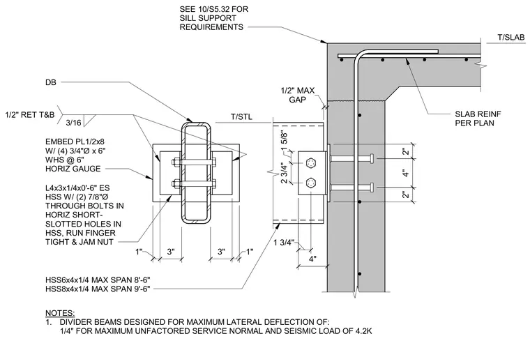
A hollow structural section divider beam connects to a concrete pit wall using an embed plate and structural steel angles. The embed plate measures one-half inch by eight inches with four three-quarter-inch diameter by six-inch welded headed studs at a six-inch horizontal gauge. A four-by-three-by-one-quarter-inch angle, six inches long each side, welds to the embed plate with a three-sixteenth-inch fillet weld top and bottom. The hollow structural section attaches to the angle with two seven-eighth-inch diameter through-bolts in horizontal short-slotted holes, installed finger tight with a jam nut. A maximum gap of one-half inch is maintained between the steel framing and the concrete wall. Slab reinforcement is provided per plan with a top of slab elevation aligned with the pit wall.
3/16 1/2" RET T&B T/SLAB SLAB REINF PER PLAN SEE 10/S5.32 FOR SILL SUPPORT REQUIREMENTS DB EMBED PL1/2x8 W/ (4) 3/4"Ø x 6" WHS @ 6" HORIZ GAUGE 2 3/4" 1 5/8" GAP 1/2" MAX L4x3x1/4x0'-6" ES HSS W/ (2) 7/8"Ø THROUGH BOLTS IN HORIZ SHORT- SLOTTED HOLES IN HSS, RUN FINGER TIGHT & JAM NUT 1" 3" 3" 1" T/STL 4" 1 3/4" 2" 4" 2" 10/S5.32 HSS6x4x1/4 MAX SPAN 8'-6" HSS8x4x1/4 MAX SPAN 9'-6" NOTES: 1. DIVIDER BEAMS DESIGNED FOR MAXIMUM LATERAL DEFLECTION OF: 1/4" FOR MAXIMUM UNFACTORED SERVICE NORMAL AND SEISMIC LOAD OF 4.2K
Members view this detail in full resolution, download the CAD files (SVG, PDF), and can adapt it in the built-in CAD editor — export DXF, DWG, or PDF.
Start membership