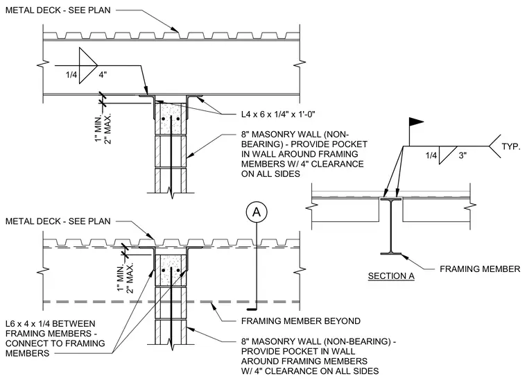
An eight-inch non-bearing masonry wall is restrained by framing members with four inches of clearance provided on all sides within a wall pocket. An L6x4x1/4 angle connects between framing members, and an L4x6x1/4 by one-foot angle ties the assembly together beneath the metal deck. A clearance of one to two inches is maintained between the top of the masonry wall and the underside of the metal deck. Fillet welds of one-quarter-inch size secure the structural steel connections as indicated.
SECTION A L6 x 4 x 1/4 BETWEEN FRAMING MEMBERS - CONNECT TO FRAMING MEMBERS 8" MASONRY WALL (NON-BEARING) - PROVIDE POCKET IN WALL AROUND FRAMING MEMBERS W/ 4" CLEARANCE ON ALL SIDES L4 x 6 x 1/4" x 1'-0" METAL DECK - SEE PLAN FRAMING MEMBER FRAMING MEMBER BEYOND 2" MAX. 1" MIN. 2" MAX. 1" MIN. 8" MASONRY WALL (NON- BEARING) - PROVIDE POCKET IN WALL AROUND FRAMING MEMBERS W/ 4" CLEARANCE ON ALL SIDES METAL DECK - SEE PLAN 1/4 3" TYP. 1/4 4" A
Members view this detail in full resolution, download the CAD files (SVG, PDF), and can adapt it in the built-in CAD editor — export DXF, DWG, or PDF.
Start membership