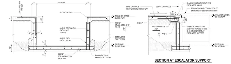
A reinforced concrete escalator pit is set within a slab on grade, featuring a depressed pit slab and formed concrete walls. The assembly is reinforced with number 4 bars spaced at twelve inches on center each way in the pit slab and continuous number 4 bars in the walls with specified concrete clearances and lap lengths. An embed plate measuring 3/4 inch by 6 inches by 1 foot 2 inches with two 3/4 inch by 6 inch headed studs at 8 inches on center is centered at the escalator support location to receive connections provided by the escalator manufacturer. The surrounding subgrade consists of compacted fill, and the top of the slab and pit elevations are coordinated per plan.
6" T/SLAB ON GRADE EL SEE PLAN #4@12" AT ALL SIDES OF PIT 2'-6" 2'-6" T #4 CONTINUOUS 1.5 T 6" T/PIT SLAB EL SEE PLAN COMPACTED FILL TYPICAL ROUGHEN TO 1/4" AMPLITUDE TYPICAL 10" 8" SEE PLAN 8" #4@12" CONTINUOUS EACH FACE TYPICAL #4@12" EACH FACE TYPICAL #4@12" TOP AND BOTTOM EACH WAY CLR 2" CLR 3" CLR 1" CLR 2" TYP UON 3/4" CLR TO BAR MIN 8" MIN 8" Ld #4 CONTINUOUS #4@12" 2'-6" 2'-6" EMBED PL3/4X6X1'-2" W/ (2) 3/4"X6" HEADED STUDS @ 8" OC CENTERED AT ESCALATOR SUPPORT (2)#4 CONTINUOUS 0' - 8" 0' - 3" T/SLAB ON GRADE EL SEE PLAN SLAB NOTCH DIMENSIONS PER ESCALATOR MANUF ESCALATOR AND CONNECTION TO EMBED PL BY ESCALATOR MANUF T/PIT SLAB EL SEE PLAN #4@12" SLAB ON GRADE REINFORCEMENT PER PLAN SECTION AT ESCALATOR SUPPORT
Members view this detail in full resolution, download the CAD files (SVG, PDF), and can adapt it in the built-in CAD editor — export DXF, DWG, or PDF.
Start membership