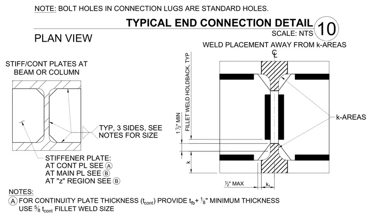
A plan view details the configuration of stiffener and continuity plates at a structural steel beam or column connection. Bolt holes in the connection lugs are specified as standard holes. Continuity plate thickness is determined by adding one-eighth inch to the beam flange thickness, with a five-eighths continuity plate fillet weld size. Welds on stiffener and continuity plates are placed away from the column k-areas, maintaining a one-half inch maximum and one-and-one-half inch minimum fillet weld holdback.
PLAN VIEW 10 TYPICAL END CONNECTION DETAIL SCALE: NTS NOTE: BOLT HOLES IN CONNECTION LUGS ARE STANDARD HOLES. FOR CONTINUITY PLATE THICKNESS (t cont ) PROVIDE t fb + 1 8 " MINIMUM THICKNESS TYP, 3 SIDES, SEE STIFFENER PLATE: A AT CONT PL SEE AT MAIN PL SEE AT "z" REGION SEE A B B NOTES FOR SIZE NOTES: USE 5 8 t cont FILLET WELD SIZE STIFF/CONT PLATES AT BEAM OR COLUMN k 1 12 " MIN FILLET WELD HOLDBACK, TYP WELD PLACEMENT AWAY FROM k-AREAS 12 " MAX k-AREAS CL k 1
Members view this detail in full resolution, download the CAD files (SVG, PDF), and can adapt it in the built-in CAD editor — export DXF, DWG, or PDF.
Start membership