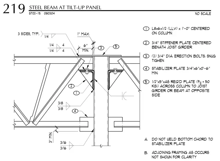
A steel joist girder frames into a hollow structural section column. The connection features an L8x6x1/2 long-leg-vertical seat angle centered on the column, secured with two three-quarter-inch diameter erection bolts tightened snug. A three-quarter-inch stiffener plate is centered beneath the joist girder, while a three-quarter-inch by six-inch by six-inch minimum stabilizer plate engages the lower chord. A one-half-inch by five-inch plate spans across the column to the joist girder or beam on the opposite side. The bottom chord is left unwelded to the stabilizer plate per the drawing notes.
ST02-19 080304 1/4 4 1/4 4 3 2 3/16 3/16 3/8 3/8 5 4 1 L8x6x1/2 (LLV) x 1'-0" CENTERED ON COLUMN 4 STABILIZER PLATE 3/4"x6"x0'-6" MIN. 5 1/2"x5"xAS REQ'D PLATE (Fy = 50 KSI) ACROSS COLUMN TO JOIST GIRDER OR BEAM AT OPPOSITE SIDE A. DO NOT WELD BOTTOM CHORD TO STABILIZER PLATE B. ADJOINING FRAMING AS OCCURS NOT SHOWN FOR CLARITY 1/4 3 SIDES, TYP. 1" MAX. 1 3" MIN. 2 3/4" STIFFENER PLATE CENTERED BENATH JOIST GIRDER 3 (2) 3/4" DIA. ERECTION BOLTS. SNUG TIGHEN MIN. 6" NO SCALE STEEL BEAM AT TILT-UP PANEL 219
Members view this detail in full resolution, download the CAD files (SVG, PDF), and can adapt it in the built-in CAD editor — export DXF, DWG, or PDF.
Start membership