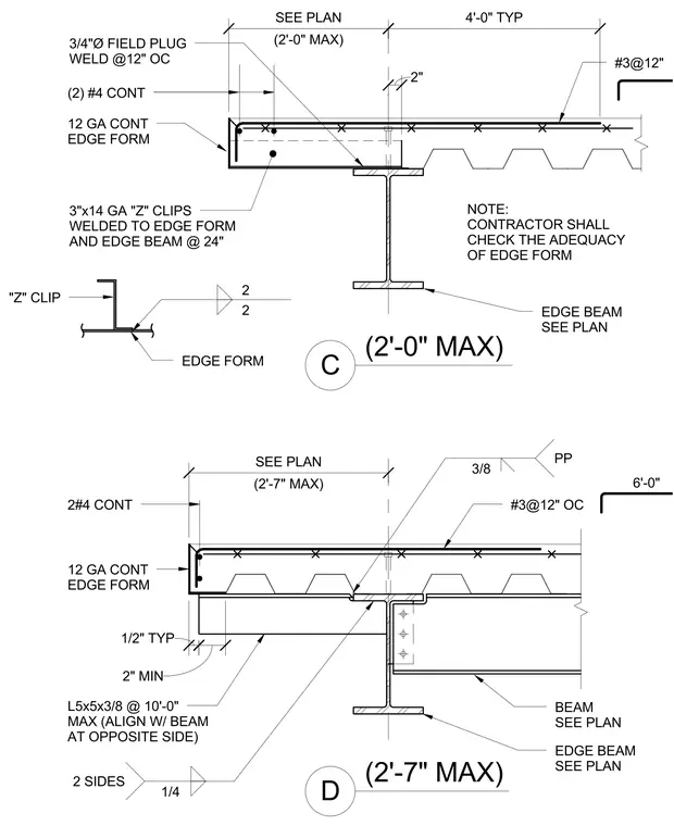
The assembly features a concrete floor slab supported by a steel edge beam and metal decking, retained by a continuous twelve gauge edge form. Three-inch by fourteen gauge Z-clips are welded to the edge form and edge beam at twenty-four inches on center. Two continuous number four rebars run longitudinally along the slab edge, supplemented by number three reinforcing bars at twelve inches on center. Three-quarter inch diameter field plug welds are spaced at twelve inches on center where indicated. Additional structural support is provided by continuous L5x5x3/8 angles spaced at ten feet maximum, aligned with the beam at the opposite side.
(2'-7" MAX) D 6'-0" 2#4 CONT L5x5x3/8 @ 10'-0" MAX (ALIGN W/ BEAM AT OPPOSITE SIDE) 12 GA CONT EDGE FORM EDGE BEAM SEE PLAN BEAM SEE PLAN #3@12" OC (2'-7" MAX) SEE PLAN (2'-0" MAX) C #3@12" 3"x14 GA "Z" CLIPS WELDED TO EDGE FORM AND EDGE BEAM @ 24" "Z" CLIP NOTE: CONTRACTOR SHALL CHECK THE ADEQUACY OF EDGE FORM EDGE BEAM SEE PLAN EDGE FORM (2) #4 CONT 12 GA CONT EDGE FORM 3/4"Ø FIELD PLUG WELD @12" OC 4'-0" TYP (2'-0" MAX) SEE PLAN 3/8 PP 1/2" TYP 2 2 1/4 2 SIDES 2" 2" MIN
Members view this detail in full resolution, download the CAD files (SVG, PDF), and can adapt it in the built-in CAD editor — export DXF, DWG, or PDF.
Start membership