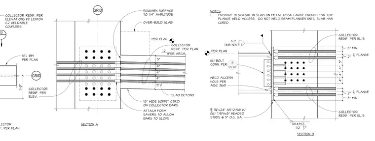
A steel beam frames into a concrete or steel support with an eighteen-inch wide centered soffit and continuous collector reinforcement. The connection utilizes a 1-1/4 inch by 24 inch A572-50 plate with sixteen 7/8 inch by 8 inch headed studs spaced at 5 inches on center gauge. Reinforcement includes Lenton C2 weldable couplers and collector bars configured per elevations and architectural plans. A weld access hole is provided per AISC 360, with a note specifying that beam flanges remain unwelded until the slab has cured, alongside a required slab blockout for top flange access.
PER PLAN PER PLAN GRID 1'-3" COLLECTOR REINF. PER ELEVATIONS W/ LENTON C2 WELDABLE COUPLERS B SECTION A SECTION B GRID 5" 4" 4" 4" 5" OVER-BUILD SLAB COLLECTOR REINF. PER PLAN ROUGHEN SURFACE TO 1/4" AMPLITUDE ATTACH FORM SAVERS TO ALLOW BARS TO SLOPE 18" WIDE SOFFIT CTR'D ON COLLECTOR BARS SLAB BEYOND COLLECTOR REINF. PER ELEV. 12 PER ARCH. & FLANGE & FLANGE 4" 4" 4" 5" 2ï" 2" 3 7/8" MIN. C.P. U.T. T&B NOTE 1. (0.435) 1/2 WELD ACCESS HOLE PER AISC 360 (6) BOLT CONN. PER 1¼"x24" A572 -50 W/ (16) 7/8"/x8" HEADED STUDS @ 5" O.C. GA. COLLECTOR REINF. PER EL.'S COLLECTOR REINF. PER EL.'S 13 S52-00 NOTES: 1. PROVIDE BLOCKOUT IN SLAB ON METAL DECK LARGE ENOUGH FOR TOP FLANGE WELD ACCESS. DO NOT WELD BEAM FLANGES UNTIL SLAB HAS CURED. STL BM PER PLAN COLLECTOR REINF. PER PLAN 2" 3" MIN. 3" 2" 2" 3" MIN. 2"
Members view this detail in full resolution, download the CAD files (SVG, PDF), and can adapt it in the built-in CAD editor — export DXF, DWG, or PDF.
Start membership