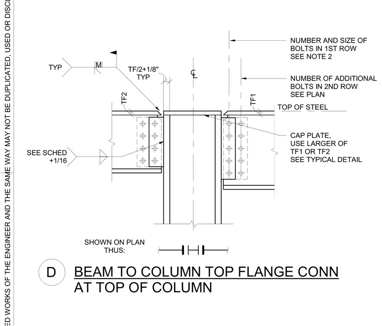
Steel beams connect to opposite sides of a structural column using bolted flange plates and a column cap plate. The cap plate thickness is sized using the larger of the connecting beam top flange thicknesses, TF1 or TF2, per the typical detail. Bolted connections feature a first row of bolts sized per structural notes and additional rows sized per plan. A gap of the top flange thickness plus one-eighth inch is maintained typically at the column centerline.
CAP PLATE, USE LARGER OF TF1 OR TF2 SEE TYPICAL DETAIL TOP OF STEEL SEE SCHED +1/16 TYP M TYP TF/2+1/8" TF2 TF1 SHOWN ON PLAN THUS: NUMBER AND SIZE OF BOLTS IN 1ST ROW SEE NOTE 2 NUMBER OF ADDITIONAL BOLTS IN 2ND ROW SEE PLAN BEAM TO COLUMN TOP FLANGE CONN AT TOP OF COLUMN D
Members view this detail in full resolution, download the CAD files (SVG, PDF), and can adapt it in the built-in CAD editor — export DXF, DWG, or PDF.
Start membership