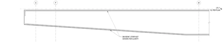
This structural section details a concrete beam framing between column lines G, P, and M at Level 1, positioned at the elevation specified per plan. The drawing indicates beam reinforcement with stirrups omitted for clarity. Grid lines and elevation markers establish the precise spatial location within the structural frame.
Members view this detail in full resolution, download the CAD files (SVG, PDF), and can adapt it in the built-in CAD editor — export DXF, DWG, or PDF.
Start membership