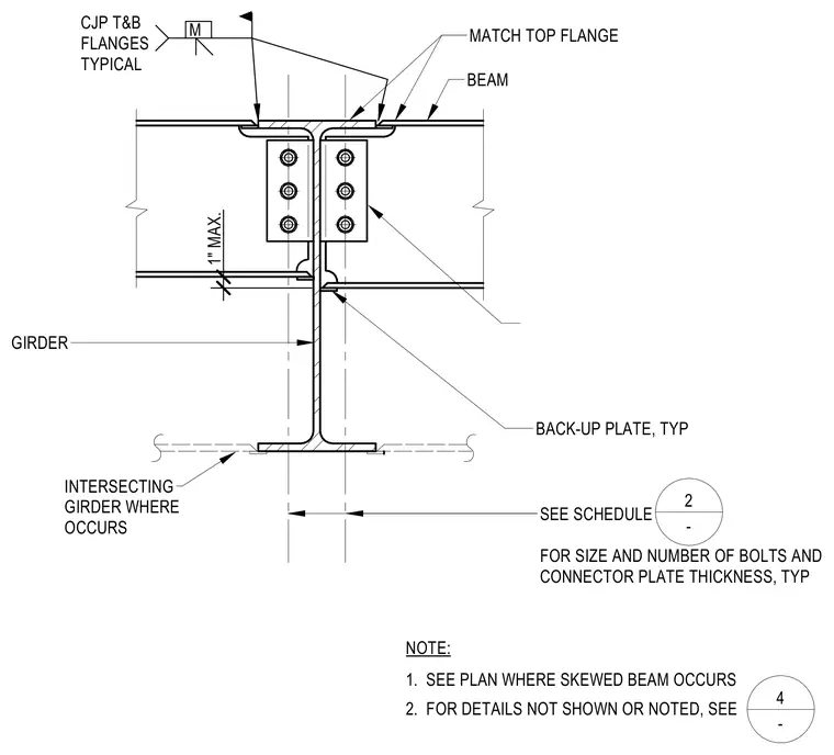
The supported steel beam connects to the girder web using bolted connector plates, with the size and number of bolts and plate thickness specified per schedule. Complete joint penetration welds are applied to the top and bottom flanges of the intersecting members, matching the top flange of the beam. A typical back-up plate is provided at the welded joint. A maximum clearance of one inch is maintained as detailed. For skewed conditions, the plan drawing and specific detail references govern.
1" MAX. NOTE: SIM. M SEE SCHEDULE FOR SIZE AND NUMBER OF BOLTS AND CONNECTOR PLATE THICKNESS, TYP INTERSECTING GIRDER WHERE OCCURS GIRDER CJP T&B FLANGES TYPICAL MATCH TOP FLANGE BEAM 1. SEE PLAN WHERE SKEWED BEAM OCCURS 2. FOR DETAILS NOT SHOWN OR NOTED, SEE BACK-UP PLATE, TYP FOR SKEWED CONNECTION SEE 9 - 2 - 4 -
Members view this detail in full resolution, download the CAD files (SVG, PDF), and can adapt it in the built-in CAD editor — export DXF, DWG, or PDF.
Start membership