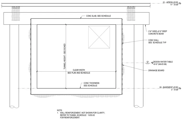
This structural section details a concrete tunnel assembly situated between the basement level at elevation 3'-9 5/8" and the apron level at 17'-9 5/8". The concrete walls and slab thicknesses are sized per the tunnel schedule, featuring a clear width and height coordinated with the structural plans. A two-foot-six-inch wide by two-foot-deep concrete beam supports the upper slab system on cast-in-place concrete columns. Drainage board is applied to the exterior face of the concrete wall below a design water table established at elevation plus eight feet relative to NAVD 88. Wall reinforcement is omitted for clarity and referenced to the tunnel schedule on drawing 13/S5.02.
01 - APRON LEVEL 17' - 9 5/8" 00 - BASEMENT LEVEL 3' - 9 5/8" CONC WALL SEE SCHEDULE TYP CONC THICKNESS SEE SCHEDULE CONC SLAB, SEE SCHEDULE SEE PLAN AND SCHEDULE CLEAR WIDTH TUNNEL HEIGHT - SEE SCHED 2'-6" WIDE x2'-0" DEEP CONCRETE BEAM 13/S5.02 DESIGN WATER TABLE +8'-0" (NAVD 88) DRAINAGE BOARD NOTE: 1. WALL REINFORCEMENT, NOT SHOWN FOR CLARITY, REFER TO TUNNEL SCHEDULE FOR REINFORCEMENT.
Members view this detail in full resolution, download the CAD files (SVG, PDF), and can adapt it in the built-in CAD editor — export DXF, DWG, or PDF.
Start membership