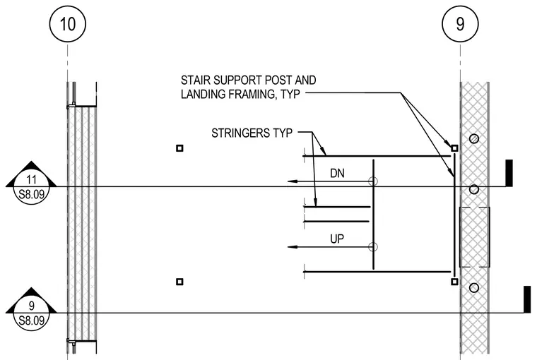
This partial plan detail shows the layout for stair stringers, typical stair support posts, and landing framing located between grid lines 9 and 10. Callouts indicate typical stair support post and landing framing as well as typical stringers with up and down directional arrows. Grid lines 9 and 10 frame the assembly along with section detail markers pointing to sheet S8.09.
9 10 9 S8.09 11 S8.09 UP DN STAIR SUPPORT POST AND LANDING FRAMING, TYP STRINGERS TYP
Members view this detail in full resolution, download the CAD files (SVG, PDF), and can adapt it in the built-in CAD editor — export DXF, DWG, or PDF.
Start membership