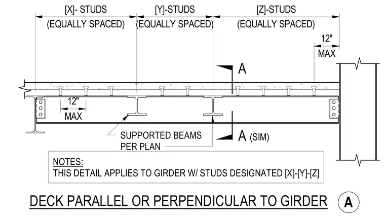
Supported beams frame into a steel girder carrying a concrete slab over metal deck. Shear studs are spaced equally across designated zones along the girder top flange with a maximum spacing of twelve inches at the ends. The detail applies to girders with stud configurations designated as X, Y, and Z per plan.
A A SUPPORTED BEAMS PER PLAN NOTES: THIS DETAIL APPLIES TO GIRDER W/ STUDS DESIGNATED [X]-[Y]-[Z] (SIM) DECK PARALLEL OR PERPENDICULAR TO GIRDER A (EQUALLY SPACED) [X]- STUDS (EQUALLY SPACED) [Y]-STUDS (EQUALLY SPACED) [Z]-STUDS MAX 12" MAX 12"
Members view this detail in full resolution, download the CAD files (SVG, PDF), and can adapt it in the built-in CAD editor — export DXF, DWG, or PDF.
Start membership